Introduction
My Volt FX-8 Li pool vac failed after one season. Although it had a warranty, the warranty was voided when I opened the "Battery Motor Box." This guide describes how to replace the failed switch and add a power transistor to handle the high current surge when the motor is turned on.
What you need
-
-
-
The premature failure of the switch is most likely related to exceeding its maximum current rating. An oscilloscope and current probe shows the voltage across the switch (red trace) and the current through the switch (yellow trace) at turn-on.
-
The peak current is about 26 A, the current exceeds 10 A for about 20 ms (large red rectangle). This peak current is determined by the battery voltage (12 V) divided by the motor resistance (0.5 ohms), 12 V / 0.5 ohm = 24 A.
-
The running (no load) current is about 2 A (small red rectangle). This current is determined by the battery voltage (12 V) minus the back EMF of the motor divided by the motor resistance.
-
The switch is rated 6 A DC (see photo).
-
Cutting the switch in half reveals a small burned spot on one of the switch contacts (see photo).
-
I also discovered that the charger adapter sometimes made a poor connection to the unit, cleaning the flat contacts solved the problem.
 Ask FixBot
-
-
-
This guide describes replacement of the damaged switch and adding a power MOSFET (Metal-Oxide Semiconductor Field-Effect Transistor) to easily switch this high current.
-
The original schematic shows that the switch handles the entire motor current.
-
The modified schematic adds a power MOSFET to switch the motor current, now the physical switch passes only a very small current.
-
The wires from the old switch now connect to the MOSFET.
-
The wires from the new switch now connect to the battery and the gate (input) of the MOSFET.
-
-
-
Remove 7 screws from primary side.
-
Remove 2 screws from secondary side.
-
Remove both sides of outer shell.
-
-
-
Remove 8 screws from motor box cover.
-
Carefully remove cover of motor box. Note that the edge of the cover is smooth, and there is a soft red gasket in the groove of the mating surface.
-
Take care not to damage or contaminate the gasket or the edge of the cover. This water-tight enclosure is important!
-
-
-
Use long-nose pliers to grip the push-on terminal connecting the red wire to the battery and pull it off of the battery terminal.
-
Tie or tape the lug so it doesn't touch the battery terminal.
-
-
-
Unscrew the knurled nut from the switch bushing (red circle).
-
Use a small screwdriver to carefully pry the latch away from the switch body (blue circle).
-
Carefully pull the switch from the switch mount.
-
Cut both switch wires leaving about 1/2" protruding from the switch body. (not shown).
-
-
-
-
Your old and new switches may vary from what is shown in this guide. This new switch has a metal nut embedded in a plastic cap with a soft cover.
-
Break the plastic pieces off of the metal switch nut.
-
Carefully compare the old and new switch. In this example the new switch is slightly thinner and slightly longer.
-
File a groove in the rear of the new switch so that the retaining clip will hold the new switch in place similar to the way it held the old switch (red circle).
-
-
-
Install the new switch so the retaining clip holds it in position (red circle).
-
Add the knurled nut (red rectangle) and tighten it so switch is secure.
-
Force hot glue into the space behind the switch (blue rectangle).
-
Add some hot glue to secure the knurled nut (not shown).
-
-
-
Place the resistor against the body of the MOSFET. (This resistor is OLD, yours may look slightly different.)
-
Wrap the resistor leads around the two outside leads of the MOSFET as shown.
-
Cut the resistor leads as shown to leave room for the wire connections.
-
Cut the two outside MOSFET leads as shown.
-
-
-
Locate the two old switch leads (Blue in the adjacent wiring diagram).
-
Cut two 1/2" long pieces of 1/8" heat shrink tubing and slide one over each lead.
-
Strip 3/16" of insulation from the end of each lead.
-
Wrap the resistor lead at the source ("S") lead of the MOSFET around the exposed portion of the old switch lead coming from the battery.
-
Solder the connection.
-
Using long-nose pliers, form a hook in the center lead (drain or "D") of the MOSFET. Form the hook around the exposed portion of the old switch lead coming from the motor.
-
Solder the connection.
-
-
-
Select one of the new switch leads (red in the adjacent wiring diagram).
-
Cut one1/2" long pieces of 1/8" heat shrink tubing and slide it over the lead.
-
Remove the pre-stripped insulation from the end of the lead. Cut the exposed wire to 3/16".
-
Wrap the resistor lead at the gate ("G") lead of the MOSFET around the exposed portion of the new switch lead.
-
Solder the connection.
-
Select the other new switch lead (red in the adjacent wiring diagram).
-
Remove the pre-stripped insulation from the end of the lead. Cut the exposed wire to 3/16".
-
Solder the lead to the positive terminal of the motor (alongside the red wire from the battery).
-
-
-
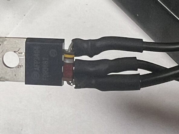
Slide the previously placed pieces of heat shrink tubing over each of the MOSFET terminals.
-
Use the butane lighter to shrink the heat shrink tubing. Apply heat to both sides of the assembly to obtain uniform shrinkage.
-
-
-
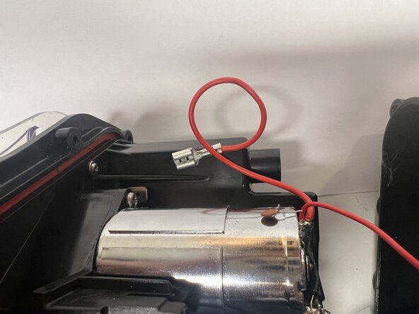
Turn the switch OFF and position the MOSFET so the metal tab is not touching any metal or wiring.
-
Momentarily touch the red wire terminal to the battery terminal.
-
If the motor did not run immediately, reconnect the red wire to the battery terminal.
-
-
-
Turn the motor on and off (push the switch) quickly several times. The on/off action should be immediate.
-
-
-
Cut a 1.5" length of 1/2" diameter heat shrink tubing.
-
Slide the heat shrink tubing over the MOSFET, connections, and small shrink tubing.
-
Use the butane lighter to shrink the tubing.
-
-
-
Slide the covered MOSFET under the center of the motor (red circle).
-
Apply the cable tie (blue lines) around the motor and the MOSFET.
-
Tighten cable tie securely.
-
Cut off protruding end of cable tie.
-
-
-
Position motor box cover for installation.
-
Install two screws on opposite sides to temporarily fasten motor box cover.
-
Turn motor on and off several times to verify operation.
-
Install and uniformly tighten all screws for motor box cover.
-
-
-
Reassemble both shells.
-
Install and tighten all screws (7 on primary side, 2 on secondary side).
-
-






Done!