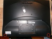
Viewsonic VG1930wm disassembly and capacitor replacement

What you need

  1. Viewsonic VG1930wm disassembly and capacitor replacement, Viewsonic VG1930wm disassembly and capacitor replacement: step 1, image 1 of 3 Viewsonic VG1930wm disassembly and capacitor replacement, Viewsonic VG1930wm disassembly and capacitor replacement: step 1, image 2 of 3 Viewsonic VG1930wm disassembly and capacitor replacement, Viewsonic VG1930wm disassembly and capacitor replacement: step 1, image 3 of 3
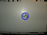
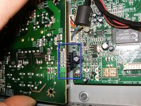
    • Here is the monitor as given to me. Not a great monitor, but the price was right.

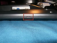
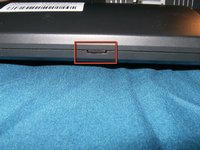
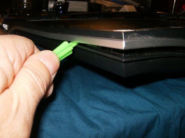
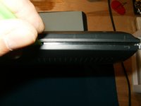
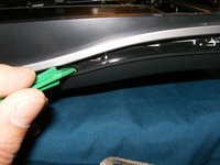
    • First to pop off the cover on the stand. Use a flat tip screwdriver, or similar tool, to pop it off

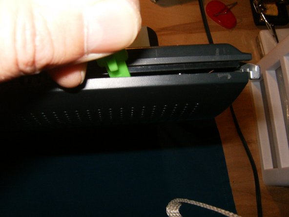
    • There are tabs where the tool can be inserted and with small force the cover will pop off

  2. Viewsonic VG1930wm disassembly and capacitor replacement: step 2, image 1 of 3 Viewsonic VG1930wm disassembly and capacitor replacement: step 2, image 2 of 3 Viewsonic VG1930wm disassembly and capacitor replacement: step 2, image 3 of 3
    • With the cover removed, the screws that hold the stand to the monitor become clearly visible.

    • Remove the four Phillips screws.

    • Remove the stand.

  3. Viewsonic VG1930wm disassembly and capacitor replacement: step 3, image 1 of 3 Viewsonic VG1930wm disassembly and capacitor replacement: step 3, image 2 of 3 Viewsonic VG1930wm disassembly and capacitor replacement: step 3, image 3 of 3
    • Remove the two Phillips screws from the back cover.

    • There are two tabs on the bottom to insert an opening tool. One on the left

    • and one on the right.

  4. Viewsonic VG1930wm disassembly and capacitor replacement: step 4, image 1 of 3 Viewsonic VG1930wm disassembly and capacitor replacement: step 4, image 2 of 3 Viewsonic VG1930wm disassembly and capacitor replacement: step 4, image 3 of 3
    • Insert a plastic opening tool in those tabs, slide the tool to the outside while exerting some side pressure.

    • This will loosen the bezel from the case.

    • Continue to move it along the opening.

  5. Viewsonic VG1930wm disassembly and capacitor replacement: step 5, image 1 of 3 Viewsonic VG1930wm disassembly and capacitor replacement: step 5, image 2 of 3 Viewsonic VG1930wm disassembly and capacitor replacement: step 5, image 3 of 3
    • The bottom will split relatively easy with the tool.

    • Start at the split bottom and continue to move along the sides.

    • The bezel will continue to split. This is the toughest part of the job and will require some patience.

  6. Viewsonic VG1930wm disassembly and capacitor replacement: step 6, image 1 of 3 Viewsonic VG1930wm disassembly and capacitor replacement: step 6, image 2 of 3 Viewsonic VG1930wm disassembly and capacitor replacement: step 6, image 3 of 3
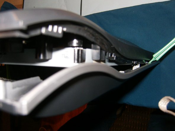
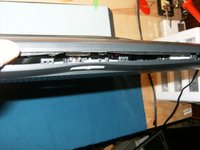
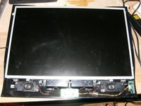
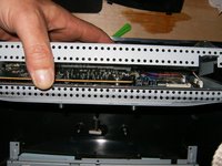
    • With the bezel remove, the front panel of the monitor becomes visible. There are no screws that hold the panel in. It is the front bezel that holds it in place.

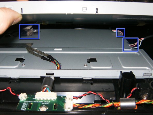
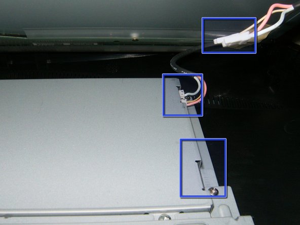
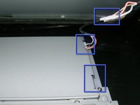
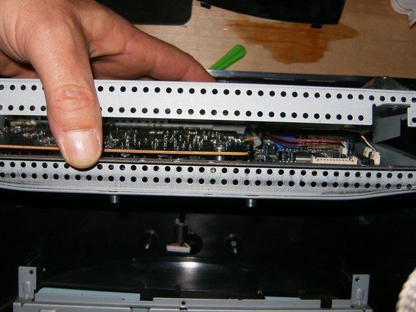
    • Carefully lift the panel on the front, there are three cables that need to be removed.

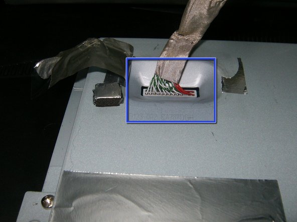
    • Remove the LVDS cable. It is a simple push connector, just pull the cable upward.

  7. Viewsonic VG1930wm disassembly and capacitor replacement: step 7, image 1 of 3 Viewsonic VG1930wm disassembly and capacitor replacement: step 7, image 2 of 3 Viewsonic VG1930wm disassembly and capacitor replacement: step 7, image 3 of 3
    • LVDS cable removed

    • CCFL cables removed

    • With the cables removed, just lift the panel up and away. The chassis and metal case for the electronic is next

  8. Viewsonic VG1930wm disassembly and capacitor replacement: step 8, image 1 of 3 Viewsonic VG1930wm disassembly and capacitor replacement: step 8, image 2 of 3 Viewsonic VG1930wm disassembly and capacitor replacement: step 8, image 3 of 3
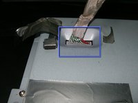
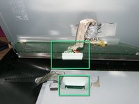
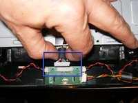
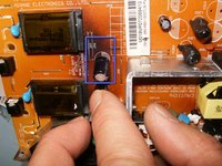
    • Remove the cable from the power button board. Again, a simple push connector, remove the cable with a gentle pull.

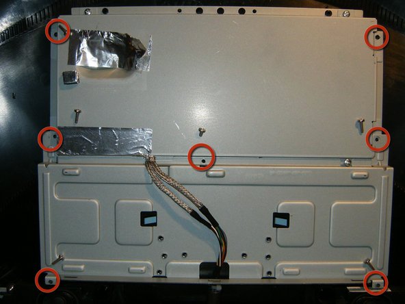
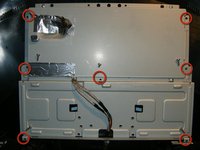
    • Remove the seven Phillips screws. The screws are all 1/2" with the exception of the center screws, that one is 1/4"

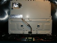
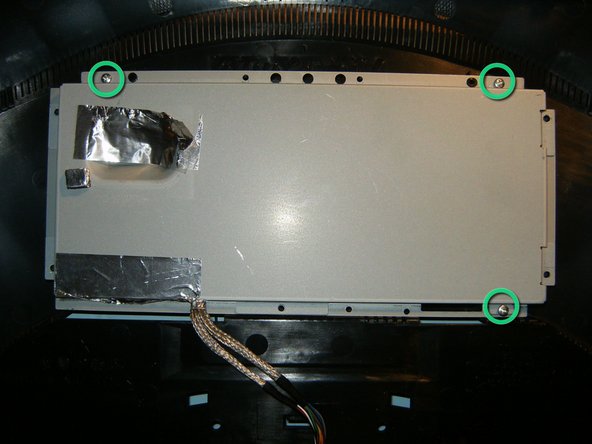
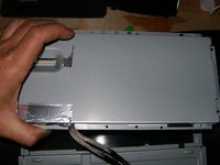
    • Remove the bottom sheet metal, this will leave the cage for the electronics. remove the three Phillips screws.

  9. Viewsonic VG1930wm disassembly and capacitor replacement: step 9, image 1 of 3 Viewsonic VG1930wm disassembly and capacitor replacement: step 9, image 2 of 3 Viewsonic VG1930wm disassembly and capacitor replacement: step 9, image 3 of 3
    • The three Phillips screws are 1/4" in length.

    • With the screws removed, the top of the cage will open,

    • and can now be separated in half.

  10. Viewsonic VG1930wm disassembly and capacitor replacement: step 10, image 1 of 3 Viewsonic VG1930wm disassembly and capacitor replacement: step 10, image 2 of 3 Viewsonic VG1930wm disassembly and capacitor replacement: step 10, image 3 of 3
    • Here is the electronics for the panel. Power board is to the left and video board to the right

    • The power board is fastened with 4 1/4 inch Phillips screws. Remove those.

    • Gently lift the board straight up, watch the connector on the right hand side.

  11. Viewsonic VG1930wm disassembly and capacitor replacement: step 11, image 1 of 3 Viewsonic VG1930wm disassembly and capacitor replacement: step 11, image 2 of 3 Viewsonic VG1930wm disassembly and capacitor replacement: step 11, image 3 of 3
    • While gently lift the power board, the ground wire becomes visible.

    • Remove the 5mmx6mm Phillips screw.

    • With the four screws and the ground wire removed, lift the power board out of the cage. The component side can now be inspected.

  12. Viewsonic VG1930wm disassembly and capacitor replacement: step 12, image 1 of 3 Viewsonic VG1930wm disassembly and capacitor replacement: step 12, image 2 of 3 Viewsonic VG1930wm disassembly and capacitor replacement: step 12, image 3 of 3
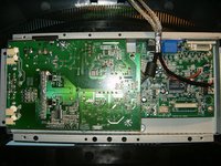
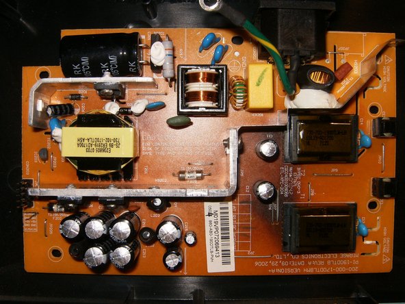
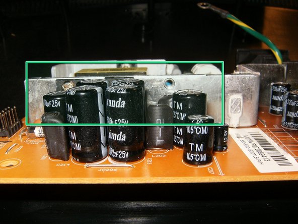
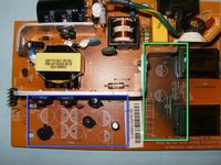
    • Here is the importance of a visual inspection.

    • Blown caps, check bulges on top of caps,

    • as well as charring on the board itself.

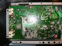
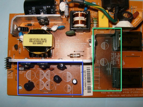
    • all of these capacitors have definitely failed. Again, check the tops for bulging.

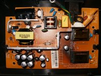
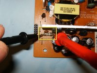
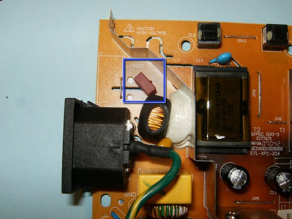
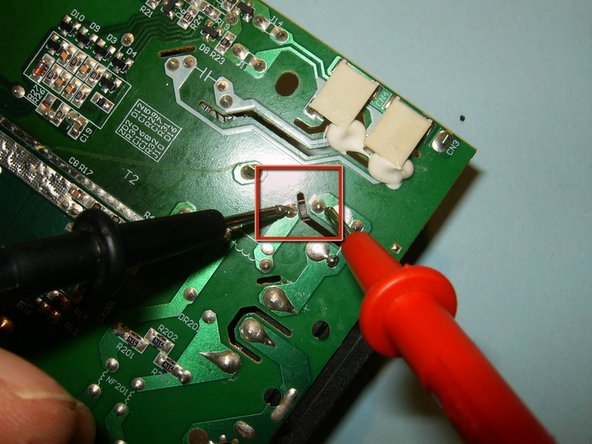
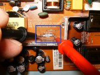
    • The power board has three fuses, those should be checked for continuity with a multimeter.

  13. Viewsonic VG1930wm disassembly and capacitor replacement: step 13, image 1 of 3 Viewsonic VG1930wm disassembly and capacitor replacement: step 13, image 2 of 3 Viewsonic VG1930wm disassembly and capacitor replacement: step 13, image 3 of 3
    • second fuse checked okay,

    • as well as the third fuse. this fuse looks a bit different,

    • and needs to be checked on the solder side of the board.

  14. Viewsonic VG1930wm disassembly and capacitor replacement: step 14, image 1 of 3 Viewsonic VG1930wm disassembly and capacitor replacement: step 14, image 2 of 3 Viewsonic VG1930wm disassembly and capacitor replacement: step 14, image 3 of 3
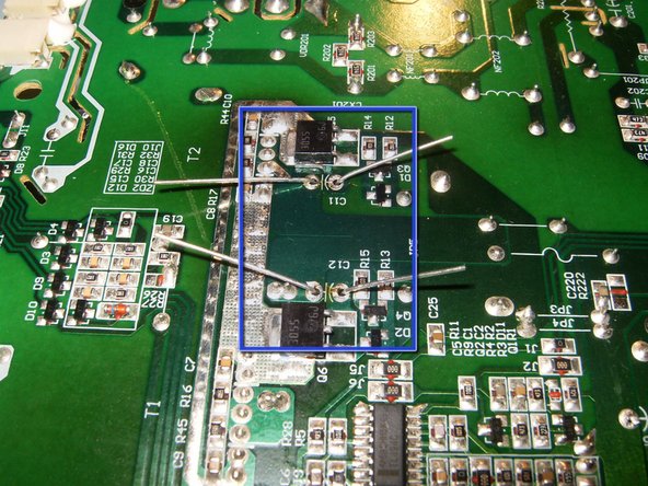
    • The solder side shows the component to be desoldered C216 470uF 25V C213 680uF 25V C214 680uF 25V C212 680uF 25V C211 680uF 25V C215 470uF 25V C217 220uF 25V C12 220uF 25V C11 220uF 25V

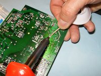
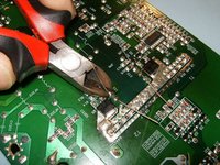
    • Desolder each cap with a solder wick, or solder sucker.

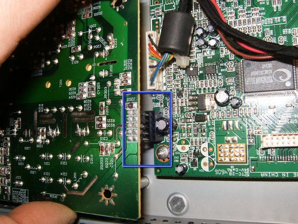
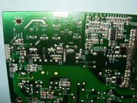
    • Logic board with all the caps removed. Note the hatched area on the logic board. This corresponds with the capacitors polarity marking. It is the negative lead, also has a shorter leg, that goes to the hatched area.

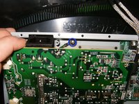
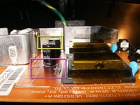
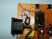
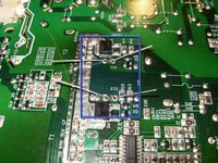
    • Clearly visible is the charred area on the logic board at the transformer side

  15. Viewsonic VG1930wm disassembly and capacitor replacement: step 15, image 1 of 3 Viewsonic VG1930wm disassembly and capacitor replacement: step 15, image 2 of 3 Viewsonic VG1930wm disassembly and capacitor replacement: step 15, image 3 of 3
    • Replace the capacitors with the appropriate ones. Watch the polarity, match shorter leg side into hatched area

    • Once the capacitors are inserted, bend the leads toward the logic board. This will ensure that the caps are tight to the board, it will also make it easier to solder them.

    • Once they are soldered, cut the excess with a pair of side cutters or equivalent. All capacitors on this board are exchanged in the same way.

  16. Viewsonic VG1930wm disassembly and capacitor replacement: step 16, image 1 of 2 Viewsonic VG1930wm disassembly and capacitor replacement: step 16, image 2 of 2
    • After reassembly of the monitor, hopefully the result will be the same. A functioning monitor:-)

Conclusion

To reassemble your device, follow these instructions in reverse order.

10 other people completed this guide.

oldturkey03

Member since: 09/29/10

776,901 Reputation

118 Guides authored

Team

Global Fixers Member of Global Fixers

Community

30 Members

517 Guides authored

4 Comments

In my case, the power board was different, and some of the internal hardware was screwed together differently, but once I could eye-ball the caps, I could identify the one that was blown, and replaced only that one. This made the monitor function as new.

Mark - Reply

Great guide, but my caps were OK. Instead IC201 has the top blown off it, ZD204 and Q201 (2SK2645) were all shorted and R217 was burnt and part of it blown out. D203 might be damaged, but likely OK.

Can anybody help / confirm the ID of any of these components? ZD204 looks to be 18V and it appears IC201 is a LD7575PS from what I can make out with the top blown off!. R217 has discoloured and a section blown away, but appears it may have been 0.35R - can anybody confirm?

Sleepwalker3 - Reply

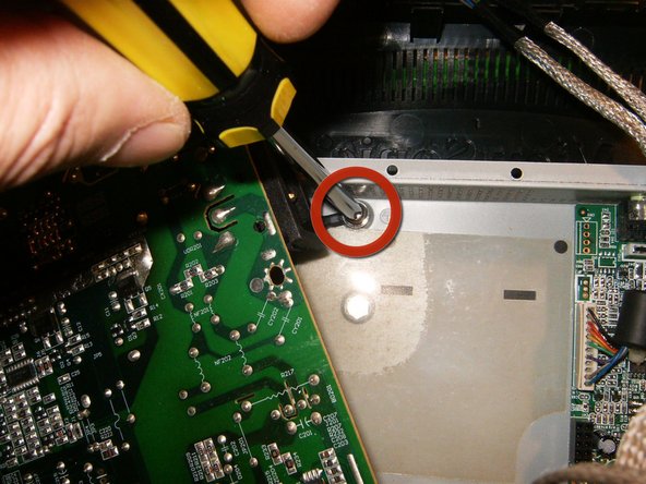
I have 5 of these monitors, and have been, for the last few years, slowly putting each of them aside as they started going bad. This week, I took one apart, using this guide, and came apart as mentioned. Sure enough, I could see the bad caps. I ordered replacements for all 5 monitors and sat down today to repair them all. The first one, done in 15 minutes or so. The 2nd one, I could not get the front bezel off. I could see there was a screw near the power button keeping the bezel attached. As it turns out, THIS vg1930wm is COMPLETELY DIFFERENT! How they can call BOTH of these monitors by the same model number is beyond me. They look so different in the way they are put together. Even the boards are different.

So if you try to follow this guide, and realize your front bezel is not coming off, flip the monitor over and remove the BACK bezel! With the screen face down, pry around the monitor as this guide shows, then there will be ONE more clip, in the center of the back bezel to pull free.

sonicvoyage - Reply

GREAT write up! I am fortunate that my monitor is exactly the same as your guide.

I found out that it's worth opening your monitor and checking quantity and type of capacitors as there are at least 2 different power board options. I blindly ordered a kit for a vg1930wm and had to swap it out for a different kit.

I barely dabble in electronics but your tutorial made this very easy. Thanks for saving me some dough.

firemedic213 - Reply

Add Comment

View Statistics:

Past 24 Hours: 2

Past 7 Days: 8

Past 30 Days: 39

All Time: 11,951