Introduction
The circuit board is an important aspect for the VTech Write and Learn Creative Center because it provides basic functionality to the device. The following repair guide addresses properly replacing a circuit board which will require soldering and the use of a screwdriver.
What you need
-
-
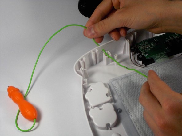
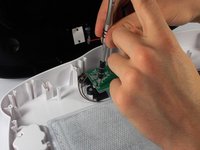
In order to remove the magnetic pen, you must desolder the two wires connecting it to the circuit board.
-
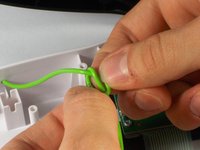
When you desolder, apply the tip of the soldering iron to the soldered joint for approximately 5 - 10 seconds.
-
The soldered joint will turn to a liquid consistency. At this moment, remove the wire and soldering iron.
-
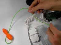
Repeat each of the following steps for the second soldered joint.
-
-
-
-
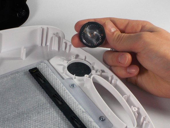
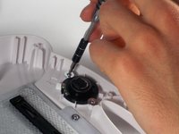
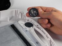
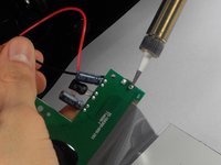
In order to remove the speaker, you must desolder the two wires connecting it to the circuit board.
-
When you desolder, apply the tip of the soldering iron to the soldered joint for approximately 5 - 10 seconds.
-
The soldered joint will turn to a liquid consistency. At this moment, remove the wire and soldering iron.
-
Repeat each of the following steps for the second soldered joint.
-
-
-
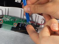
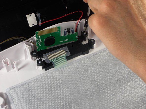
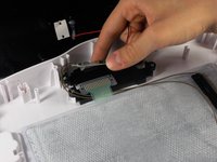
The first part of this step is to remove the hot glue from the base of the wires using the plastic opening tool.
-
The next step if to remove the two 7 mm long PH0 Phillips screws holding the board in.
-


To reassemble your device, follow these instructions in reverse order.
Team

UMass Dartmouth, Team 1-2, Miles Spring 2016 Member of UMass Dartmouth, Team 1-2, Miles Spring 2016
UMASSD-MILES-S16S1G2
3 Members
12 Guides authored
3 Guide Comments
This explains how to remove the mother board, but how do you fix the issue at hand??
Do you have a telephone number that I could call to find out what the problem could be, the table turns on but then shuts down I've changed the batteries and still does the same thing. Please help me, simmybrown1234@yahoo.com
Okay so I have taken this thing apart and I see a black spot on the mother board and red lines going through the ribbon I'm guessing it's fried…..let me know if you get this message so I know weather or not I can toss this toy…..and I'm not wasting my time trying to fix it….thank you…