Introduction
This guide covers the removal of the main LCD screen and associated housing from the Toshiba A1304T for replacement.
What you need
-
-
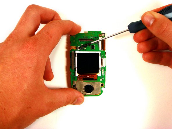
Open the phone so that it matches the photos to the left.
-
Using a thumb-tack, push-pin, or similar pin, remove the four plastic stoppers located around the main LCD screen.
-
-
-
With the T8 Torx Security Bit Screwdriver, remove the four screws in the designated locations.
-
-
-
-
Insert the head of a flathead screwdriver into the seam between the front cover and the phone.
-
Pry gently until the cover gives slightly to create a slightly wider opening. You may hear a distinct pop as you pry.
-
Remove the screwdriver and re-insert it into another portion of the seam. Continue making gaps around the cover of the phone until it is completely detached from the body.
-
-
-
Using the head of the flathead screwdriver, gently pry the black tab so that it rests in a vertical (or "unlocked") position.
-
Pull the orange ribbon-wire to the left, removing it from the white socket.
-
-
-
Just as before, use the head of the flathead screwdriver to pry the black tab into a vertical position, as shown.
-
Pull the ribbon wire to the right, freeing it from its socket.
-
-
-
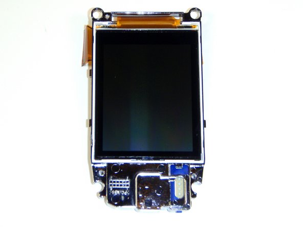
Using the head of the flathead screwdriver, pry the silver plastic casing of the LCD from the video logic board.
-
Repeat as necessary around the device until the silver plastic casing is free.
-


Team

Cal Poly, Team 16-6, Maness Spring 2010 Member of Cal Poly, Team 16-6, Maness Spring 2010
CPSU-MANESS-S10S16G6
4 Members
16 Guides authored