Introduction
How about plugging a single barrel conector (just like the original) to your Atari 1050 floppy drive, but with 12v DC instead of 9v AC?
Background:
The original 9V AC power supply brick required for these drives are slowly vanishing from the surface of the planet. They are bulky, heavy, and increasingly harder to find.
We will perform a definitive conversion of your drive so it can operate with a more convenient, lightweight and readily available / standard 12V DC power supply.
What is this modification about:
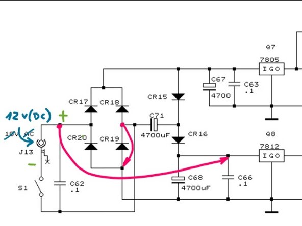
It consists of simply adding two jumper wires that will disable both the rectifying circuit and the voltage doubler. This will allow the drive to work with power supplies in the range of 12v -16v DC, while working safely within lower voltage and temperature ranges.
Why this mod:
- This is a very simple mod in concept. But it will require a steady pulse on your end and a soldering station. I prefer to do this mod on the soldering side of the board, but I made this guide with a top-board approach in mind so you don't have to disassemble any further than strictly necessary.
- This mod is easily reversible if you ever want to take your drive back to its factory settings.
- It allows your drive to work well within noise and temperature parameters. Your drive should work and be healthy for years.
- Other mods disable the power switch. With this mod the switch works just as intended.
- It is safe (not foolproof though): This mod will still rely on the original voltage regulators. This is important because they will serve as protection to your drive in the event you ever plug one of the old 9V AC power supplies by accident.
- Solderless option: If you don't feel comfortable soldering, you may perform this mod in 10 minutes without even soldering.
About me: I am not an electronics professional, but I do have formal studies in electronics and I have repaired and tinkered with Atari gear for decades.
What you need
-
-
What you will need:
-
A 12v, 13v, 14v, 15v, or 16v, 2.5 Amp DC capable power supply with a center positive 2.5mm barrel connector plug at the end. I prefer 12v since these are very common these days because they come with home WiFi equipment that gets renewed quite frequently.
-
A labeler machine or printer (for the warning sticker). This is important, I'll tell you more about that later.
-
Hemostats. These are highly recommended because you will have to solder in places that are not easy to reach.
-
A soldering station capable of 330°C. This temperature setting is relevant because you will solder on elements capable of dissipating heat.
-
A small screwdriver for calibrating the motor speed.
-
A copy of 1050 disk drive diagnostics diskette for final tests and calibration. Find the software here and have it ready before beginning: https://archive.org/details/a8b_1050_Dis...
-
-
-
If you don't have a soldering iron or don't feel comfortable soldering, you can get this done with circuit test hooks!
-
Just make sure there's a firm connection to either the leg of the voltage regulator or the leg of each diode depending on the connection you are making.
-
You will find these under names such as mini clips, SMD IC spring hooks, test leads for logic analyzer and such.
-
These are usually rated for 60v / 3A so they will do the job.
-
-
-
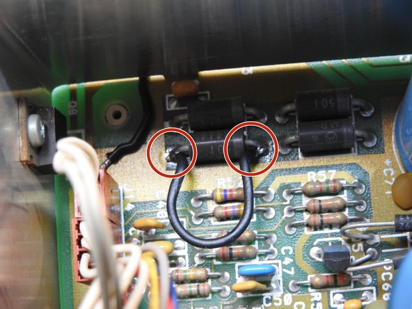
Take a look at the diagram: You are about to add the two jumper wires highlighted in red.
-
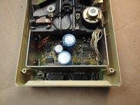
Prepare your Atari 1050 on a clean surface. Put a towel on top of the table to prevent scratches to the unit.
-
Remove all 6 philips screws on the underside of the unit
-
Flip the unit back on its feet and carefully remove both the top and front cover as if they were one single piece. Be gentle: This plastic is over 40 years old.
-
Place the drive in a way the SIO connectors are facing away from you and the front panel is facing you.
-
-
-
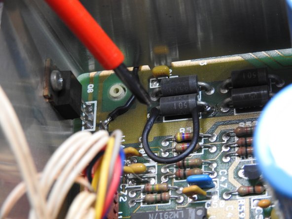
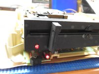
With the SIO connectors facing away from you and the front of the unit facing you, locate the four diodes.
-
Preferably, use 20 AWG wire for the connections.
-
Solder the first bridge on top of the CR19, which is one of the 4 large diodes (the one at the bottom left)
-
-
-
-
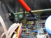
With the help of pliers or hemostats, grab and pull the J14 connector out, which is the first on the row. This step is not required, but recommended.
-
Since you will solder right next to this connector, removing it is a cautionary measure so you have more room and you don't melt this connector by accident.
-
-
-
One end of this jumper wire will be soldered to the diode at the top right. Don't worry if it touches the diode to its left as these two are connected from factory.
-
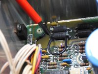
The other end of the jumper wire, will go to the input of the 12v regulator. There is a convenient pad right next to it you can use.
-
Connecting to the output of the 12v regulator: If you use a good quality, regulated 12v power supply, you can actually connect this end of the wire to the OUTPUT of the 12V regulator for lower thermal operation (located at TP14) however,
-
by using the input pin as indicated here, you will be able to use a power supply higher than 12v, and also, the 12v regulator will serve as protection in case anything goes wrong with your power supply or for when someone accidentally connects an old 9V AC power brick to your drive.
-
-
-
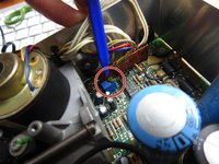
After finishing with the soldering, re-connect J14 right where it belongs.
-
-
-
Chances are your drive is in working condition by now, ready to take the new 12v power supply. So, plug it in and give it a go!
-
At this point, the speed of the spinning motor may be slightly altered. So let's take care of that in this step.
-
Locate the adjusting trimpot. There is a chance it comes with silicon coating on top. Break it off gently with your hemostats until you can access the small brass screw with a flat screwdriver.
-
Load your 1050 diagnostic diskette and adjust the trimpot to the desired speed.
-
-
-
You are almost finished. Reassemble the case and put the screws back in.
-
Print a label that clearly states that your drive now takes 12V DC center positive. Don't call this project finished without this step.
-
You want to avoid any confusion or someone plugging in an old AC power supply to this modified drive.
-
For DC, you can actually go higher in voltage, all the way to 15v, even 18v. The power section of the drive may heat up a bit, but it will work regardless, with minimal risk.
-
Still, you must stick to DC, not AC so the label is a MUST.
-
-
-
For the electronics enthusiasts, I took some measurements so you don't have to. Here are the facts:
-
12v rail voltage: The 12v regulator will read 12v at the input, and close to 10.6v at the output. This is OK for the drive. If there is any drop in motor speed, you may correct it with the trim pot adjustment. Just remember you may as well connect the 12v line to the output of the regulator.
-
5v rail voltage: The 5v regulator will read close to 11.2v at the input and 5.0v at the output. This is OK and the stock heat dissipator will take care of the heat.
-
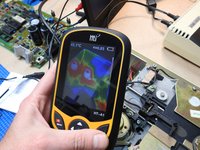
Temperature: After 20 minutes at 22°C ambient temp, the 12v regulator reads 37°C and the 5v regulator reads 47°C . This is all well within operating range.
-
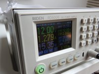
Current: After switching on, the current drawn from the new power supply reads 630mA (which is normal since it feeds all the electronics circuitry). When the motors are in operation, the total current reads 1,170mA (~1.2 Amps).
-
Heat: Your unit will now produce less heat: Since you disabled the voltage doubler, the 12v reg has very little work to do now, and thus, less heat to dissipate. The 5v reg has to drop 0.3v more than before, almost negligible.
-
The current readings above, mean that any nominal 12v/2A or better yet 2.5A DC power supply will be powerful enough.
-
Equipment used for taking measurements: Fluke 87V multimeter, Rigol DS 1054Z scope, HTI thermal camera.
-


Enjoy your modernized floppy drive, feel free to contact me and contribute to make this tutorial better or clearer.
Cancel: I did not complete this guide.
2 other people completed this guide.
