Introduction
Disclaimer: I am by no means an expert in this area of repair, and some of my methods may be a little hacky. Regardless, I have tested these instructions and can confirm that they work perfectly fine.
What you need
-
-
Turn the calculator so that the backside is facing up.
-
Remove the battery cover and also the batteries.
-
Use a Philips Screwdriver to unscrew the RAM Backup Battery cover and then remove the CR1616 Coin Battery from inside.
-
Use a T6 Torx Screwdriver to remove the 6 Torx Screws from the calculator.
-
-
-
Using a spudger, gently pry open the calculator.
-
Once opened, you should see the IO port at the bottom of the motherboard as shown on the image. Now is a good time to have your soldering iron ready.
-
-
-
Tool used on this step:Tweezers$4.99
-
Insert a thin piece of metal, such as a pair of tweezers, into the IO port and gently apply pressure pushing away from the circuit board. You will need to do this throughout the whole process of desoldering.
-
Using a soldering iron, carefully heat up the 3 pads that are soldered to the IO Port. It should come off pretty easily provided you are applying pressure like described above.
-
-
-
If using a genuine port replacement, simply solder it on to the pads. Take care not to burn any of the pads off.
-
If using a generic port, a little more work is required. Use a bit of Blu-tack or something else sticky but easily removable to fix the headphone jack in place.
-
Then, you will want to snip the leads off of 2 resistors - these will be our jumper wires.
-
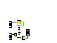
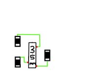
If you burnt the pads off whilst desoldering, or whilst attempting to solder, you can still solder to the nearby components if you are careful, as shown in Image 2. Otherwise, simply solder 1 end of a jumper wire to a pin on the headphone jack, and the other end to its corresponding solder pad.
-
Repeat the above for all 3 pins. In the end it should look like one of the above images, with blue lines being nearby traces which you can ignore, and green lines being your resistor-lead jumper wires.
-


To reassemble your device, follow these instructions in reverse order.
Cancel: I did not complete this guide.
One other person completed this guide.

1 Guide Comment
Mi calculadora funcionaba sin problema y transferia todo a una TI-84 Silver Edition, pero no se que sucedio, que esta ultima vez, al tratar de conectarlas, al principio si copiaron la mayoria de archivos, pero al final me mando mensaje de "error en la transmision". Lo intente varias ocasiones, incluso revise el cable y no tiene problema, No me queda mas que abrirla y seguir este procedimiento. Muchas gracias!!!