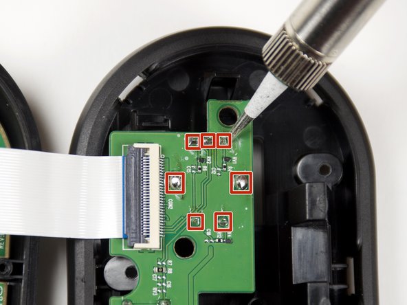
SteelSeries Arctis Pro Plus GameDAC Potentiometer Replacement

What you need

  1. SteelSeries Arctis Pro Plus GameDAC Potentiometer Replacement, GameDAC Potentiometer: step 1, image 1 of 3 SteelSeries Arctis Pro Plus GameDAC Potentiometer Replacement, GameDAC Potentiometer: step 1, image 2 of 3 SteelSeries Arctis Pro Plus GameDAC Potentiometer Replacement, GameDAC Potentiometer: step 1, image 3 of 3
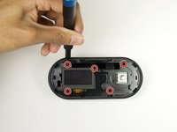
    • Remove the plastic cover using the iFixit opening tool to pry the cover open.

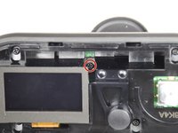
    • Insert opening picks to keep the cover open as you work your way around the GameDAC.
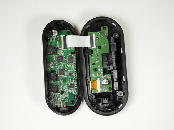
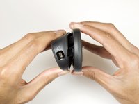
    • Pop the cover off.

  2. SteelSeries Arctis Pro Plus GameDAC Potentiometer Replacement: step 2, image 1 of 2 SteelSeries Arctis Pro Plus GameDAC Potentiometer Replacement: step 2, image 2 of 2
    • Remove the control wheel from the GameDAC by pulling on the knob.

  3. SteelSeries Arctis Pro Plus GameDAC Potentiometer Replacement: step 3, image 1 of 2 SteelSeries Arctis Pro Plus GameDAC Potentiometer Replacement: step 3, image 2 of 2
    • Remove the five 6mm screws using the Phillips #0 driver head.

    • There is one screw hidden on the upper right-hand side of the display.

  4. SteelSeries Arctis Pro Plus GameDAC Potentiometer Replacement: step 4, image 1 of 2 SteelSeries Arctis Pro Plus GameDAC Potentiometer Replacement: step 4, image 2 of 2
    • Hold the sides of the GameDAC and pull apart.

    • Don't pull the two sides apart quickly or forcefully to avoid tearing the wire connection between the two boards.

  5. SteelSeries Arctis Pro Plus GameDAC Potentiometer Replacement: step 5, image 1 of 1
    • Remove the three 4mm screws from the circuit board using the Phillips #0 driver head.

  6. SteelSeries Arctis Pro Plus GameDAC Potentiometer Replacement: step 6, image 1 of 2 SteelSeries Arctis Pro Plus GameDAC Potentiometer Replacement: step 6, image 2 of 2
    • Desolder the seven potentiometer pins from the board to remove the button.

    • For help desoldering connections, follow this useful guide on How To Solder and Desolder Connections.

    • Use caution when soldering. The heated tip may cause damage to the board or burn you.

Conclusion

To reassemble your device, follow these instructions in reverse order.

5 other people completed this guide.

Avinash Vadlamudi

Member since: 01/24/19

451 Reputation

1 Guide authored

Team

Cal Poly, Team S18-G1, White Winter 2019 Member of Cal Poly, Team S18-G1, White Winter 2019

CPSU-WHITE-W19S18G1

4 Members

21 Guides authored

3 Comments

Hi there,

do you know what type of potentiometer is needed?

Greetings

Chris

Christian Humann - Reply

I would like to know too. Cause it failed for me as well!!

Antonis Lazarakis - Reply

Can I replace the Oled Screen with 2,42 inch arduino oled display that also have 24pin flex?

Muso!27 - Reply

Add Comment

View Statistics:

Past 24 Hours: 1

Past 7 Days: 24

Past 30 Days: 79

All Time: 4,417