Free Shipping on Domestic Orders $75+

Sigrow Soil Pro + Assembly

What you need

    1. Sigrow Soil Pro + Assembly, Gather materials: step 1, image 1 of 3 Sigrow Soil Pro + Assembly, Gather materials: step 1, image 2 of 3 Sigrow Soil Pro + Assembly, Gather materials: step 1, image 3 of 3
      • PCB RR02 or higher 'coated

      • Sigrow Soil Sensor

      • (Top left to bottom right) Case Body +, hat +, solar, bottom inner plate +, fan holder.

      • Sunon Fan 5VDC

      • Solar panel 110x80

      • Tools (top-left to bottom right) : tin, soldering station, flat head screw driver, cable peeler, pliers glue gun (optional).

      • Cable double insulaton: +6 wires, 20 cm

      Ask FixBot

      Add Comment

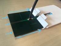
    2. Sigrow Soil Pro + Assembly, Prepare cable solar panel to PCB: step 2, image 1 of 3 Sigrow Soil Pro + Assembly, Prepare cable solar panel to PCB: step 2, image 2 of 3 Sigrow Soil Pro + Assembly, Prepare cable solar panel to PCB: step 2, image 3 of 3
      • Cable length is aprox 20-22 cm

      • Peel both ends, keep the non-peeled part short

      • Group them, twist and solder them together

      • On the opposite side you will only keep two colours: black and yellow

      Ask FixBot

      Add Comment

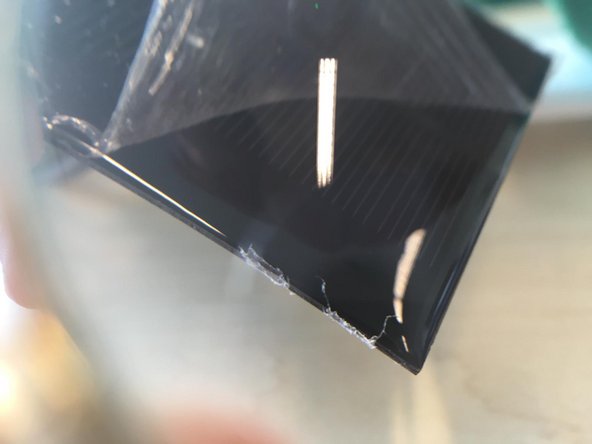
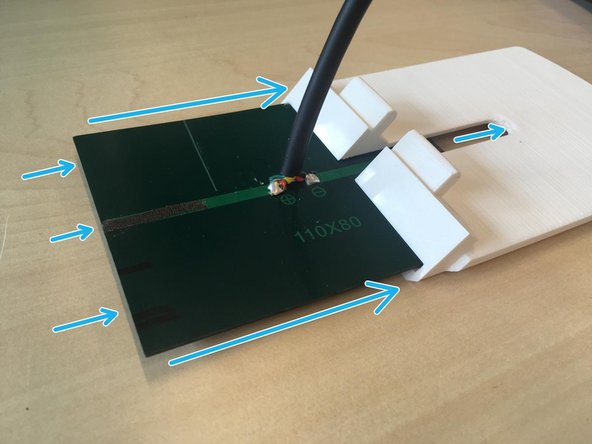
    3. Sigrow Soil Pro + Assembly, Solder cable solar panel: step 3, image 1 of 3 Sigrow Soil Pro + Assembly, Solder cable solar panel: step 3, image 2 of 3 Sigrow Soil Pro + Assembly, Solder cable solar panel: step 3, image 3 of 3
      • Solder

      • Remove the plastic sheet

      • Slide solar panel in parasol

      Ask FixBot

      Add Comment

    4. Sigrow Soil Pro + Assembly, Fan mount: step 4, image 1 of 1
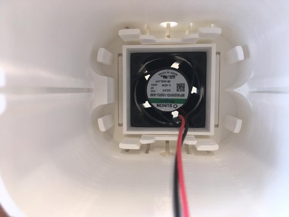
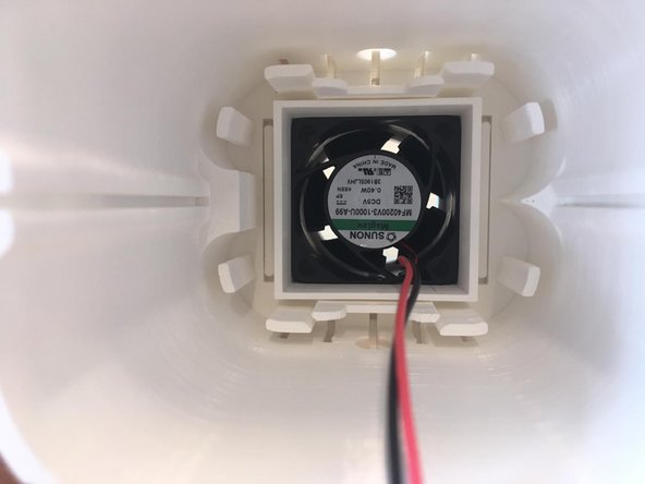
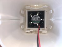
      • Insert fan in fan holder

      • Pay attention to the fan air flow direction, it should be upwards

      Ask FixBot

      Add Comment

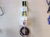
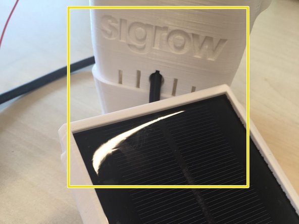
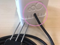
    5. Sigrow Soil Pro + Assembly, Peripherals: step 5, image 1 of 2 Sigrow Soil Pro + Assembly, Peripherals: step 5, image 2 of 2
      • From top to bottom:

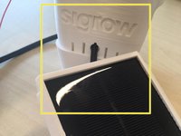
      • Solar Panel mounted and with cable soldered (side with Sigrow letters)

      • Fan (cable enters from bottom)

      • Soil Sensor (cable enters from Sigrow 3 circles logo side)

      Ask FixBot

      Add Comment

    6. Sigrow Soil Pro + Assembly, Attach fan holder to main case+: step 6, image 1 of 2 Sigrow Soil Pro + Assembly, Attach fan holder to main case+: step 6, image 2 of 2
      • Fan holder should be inserted in main body case by pressure

      • If there's not a tight fit there are 2 options:

      • Option 1: Request a new fan holder

      • Option 2: Use the hot glue gun.

      • tight fit could be interpreted as: "if with very hard shaken the fan holder and main case will not disconnect and stay solidly attached.'

      Ask FixBot

      Add Comment

    7. Sigrow Soil Pro + Assembly, Bottom inner plate: step 7, image 1 of 2 Sigrow Soil Pro + Assembly, Bottom inner plate: step 7, image 2 of 2
      • Rectangular gap (for temperature humidity sensor) goes slightly in the left.

      • Bottom right tiny circular hole is for the fan cables

      Ask FixBot

      Add Comment

    8. Sigrow Soil Pro + Assembly, Confirm orientation: step 8, image 1 of 2 Sigrow Soil Pro + Assembly, Confirm orientation: step 8, image 2 of 2
      • Sigrow 3 circles side-> Soil Sensor

      • Letter side -> Solar panel

      Ask FixBot

      Add Comment

    9. Sigrow Soil Pro + Assembly, Soil Sensor connection: step 9, image 1 of 3 Sigrow Soil Pro + Assembly, Soil Sensor connection: step 9, image 2 of 3 Sigrow Soil Pro + Assembly, Soil Sensor connection: step 9, image 3 of 3
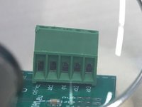
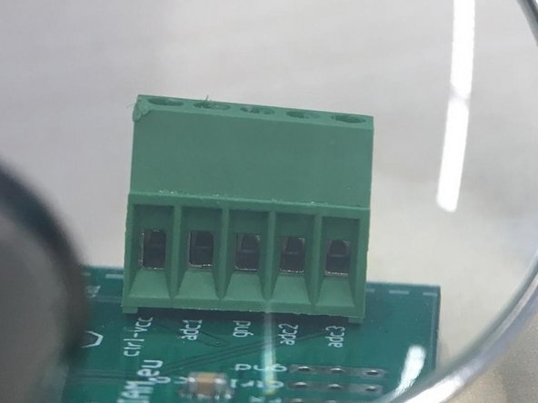
      • Insert cables into connector, check in 3rd image in this step that the ports are open

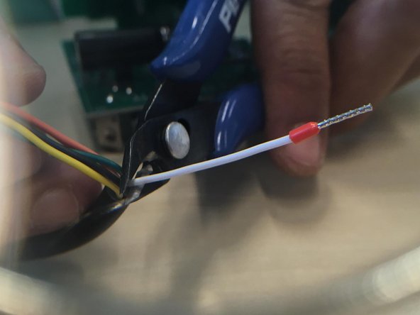
      • Use pliers to cut white cable

      Ask FixBot

      Add Comment

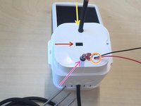
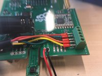
    10. Sigrow Soil Pro + Assembly, Solder fan cables: step 10, image 1 of 2 Sigrow Soil Pro + Assembly, Solder fan cables: step 10, image 2 of 2
      • Black ground

      • Red positive

      • Cut with pliers cable excess from behind

      Ask FixBot

      Add Comment

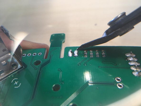
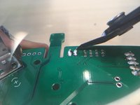
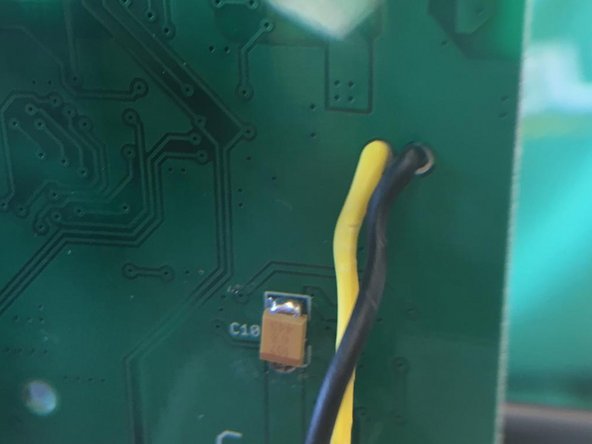
    11. Sigrow Soil Pro + Assembly, Solder solar panel cables to pcb: step 11, image 1 of 3 Sigrow Soil Pro + Assembly, Solder solar panel cables to pcb: step 11, image 2 of 3 Sigrow Soil Pro + Assembly, Solder solar panel cables to pcb: step 11, image 3 of 3
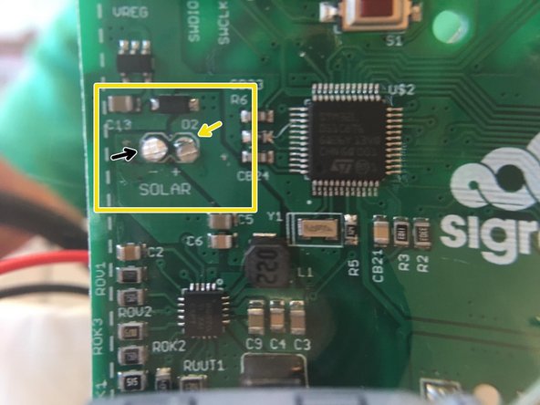
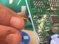
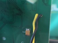
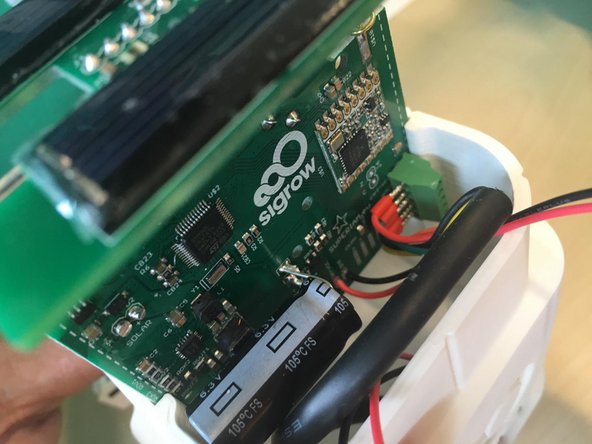
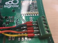
      • Cables enter from the back of the PCB

      • Yellow is positive

      • Black is negative (closer to the edge)

      • Cut with pliers cable and tin excess

      • Soldering station is very hot, dont touch it with your hands

      Ask FixBot

      Add Comment

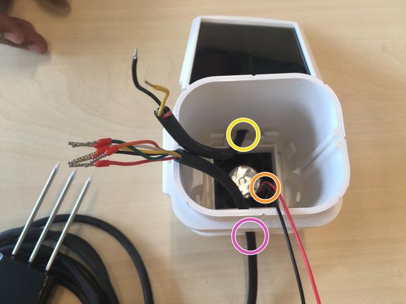
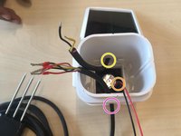
    12. Sigrow Soil Pro + Assembly, Insert PCB in case - Cable details: step 12, image 1 of 2 Sigrow Soil Pro + Assembly, Insert PCB in case - Cable details: step 12, image 2 of 2
      • It's great to leave some extra cables in good shape

      • ~10 cm for the soil sensor bended as inverted-U

      • Twist the fan cable (it's very long) and bend as inverted-U

      • if PCB doesn't slide down with a gentle push or slides out too easy when case is upside down new case should be requested.

      Ask FixBot

      Add Comment

    13. Sigrow Soil Pro + Assembly, Closing the case: step 13, image 1 of 2 Sigrow Soil Pro + Assembly, Closing the case: step 13, image 2 of 2
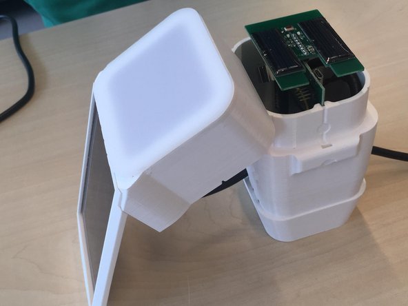
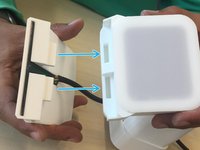
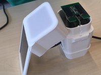
      • After sliding PCB in, connect the solar parasol and the hat +

      • If the fit is not great inform Sigrow senior technician

      Ask FixBot

      Add Comment

    14. Sigrow Soil Pro + Assembly: step 14, image 1 of 1
      • Congrats, you have completed a Soil Pro+

      • Please request from your Senior technician the latest packaging guidelines

      Ask FixBot

      Add Comment

Conclusion

In case of doubt contact manufacturing@sigrow.com

Cancel: I did not complete this guide.

Sigrow

Member since: 05/14/20

1,086 Reputation

5 Guides authored

Team

Sigrow Member of Sigrow

Community

3 Members

59 Guides authored

0 Guide Comments

Add Comment

View Statistics:

Past 24 Hours: 2

Past 7 Days: 12

Past 30 Days: 33

All Time: 424