
Separating Main Board

What you need

  1. Separating Main Board, Remove Battery: step 1, image 1 of 3 Separating Main Board, Remove Battery: step 1, image 2 of 3 Separating Main Board, Remove Battery: step 1, image 3 of 3
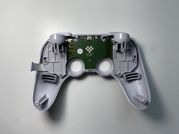
    • Place the controller face down.

    • Remove the battery cover.

    • Remove rechargeable battery or AA batteries.

  2. Separating Main Board, Remove Trigger Buttons: step 2, image 1 of 2 Separating Main Board, Remove Trigger Buttons: step 2, image 2 of 2
    • Remove L2 and R2 trigger buttons by pushing them away from the grips.

  3. Separating Main Board, Remove Screws: step 3, image 1 of 2 Separating Main Board, Remove Screws: step 3, image 2 of 2
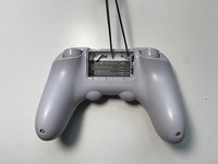
    • Use Tweezers to uncover two screws under the label in the battery compartment.

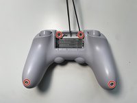
    • Use a T6 screwdriver to remove the four 7.3 mm screws securing the rear cover.

  4. Separating Main Board, Unclip Covers: step 4, image 1 of 3 Separating Main Board, Unclip Covers: step 4, image 2 of 3 Separating Main Board, Unclip Covers: step 4, image 3 of 3
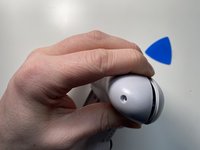
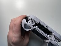
    • At the end of each grip, pry apart the covers.

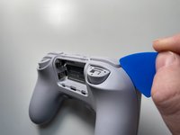
    • Use fingernail or opening pick to undo the two top clips.

    • One clip next to L button.

    • One clip next to R button

    • Undo the final clip between the joysticks.

  5. Separating Main Board, Separate Covers: step 5, image 1 of 1
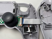
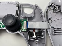
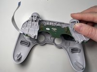
    • Carefully move the rear cover away and from the front cover. Place it to the left.

    • Do not completely separate. The two halves are still attached via a white ribbon cable.

  6. Separating Main Board, Remove Ribbon Cable: step 6, image 1 of 3 Separating Main Board, Remove Ribbon Cable: step 6, image 2 of 3 Separating Main Board, Remove Ribbon Cable: step 6, image 3 of 3
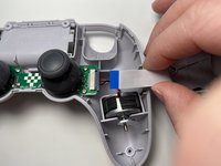
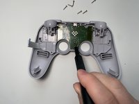
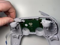
    • Unlock the ribbon cable by push open the black plastic tab.

    • The tab will slide about 1.5mm

    • Pull the ribbon cable out of the connector in the direction of the cable.

  7. Separating Main Board, Remove Screws: step 7, image 1 of 3 Separating Main Board, Remove Screws: step 7, image 2 of 3 Separating Main Board, Remove Screws: step 7, image 3 of 3
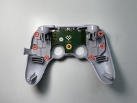
    • Use a Phillips screwdriver to remove the seven screws securing the main circuit board.

    • Six 10.1mm screws

    • One 5.8mm screws

  8. Separating Main Board, Separate Main Board: step 8, image 1 of 3 Separating Main Board, Separate Main Board: step 8, image 2 of 3 Separating Main Board, Separate Main Board: step 8, image 3 of 3
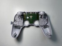
    • Slide the R buttons up and off its peg.

    • Slide the L button up and off its peg.

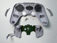
    • Remove the main board by rotating it towards the USB-C port. Then lift it out.

Conclusion

To reassemble your device, follow these instructions in reverse order.

Brian W

Member since: 12/21/11

1,290 Reputation

8 Guides authored

One Comment

if you need a replacement ribbon the specs are

length: 70mm

pitch: 0.5mm

pins: 20

forward side pinning (that means the contacts are on the same side)

some listings add the total width, thats 20.5mm

Max R. - Reply

Add Comment

View Statistics:

Past 24 Hours: 1

Past 7 Days: 5

Past 30 Days: 16

All Time: 529