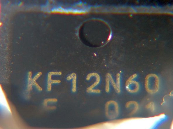
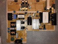
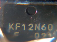
Samsung LS32D85KTSR Power Supply Replacement

What you need

  1. Samsung LS32D85KTSR Power Supply Replacement, Power Supply: step 1, image 1 of 3 Samsung LS32D85KTSR Power Supply Replacement, Power Supply: step 1, image 2 of 3 Samsung LS32D85KTSR Power Supply Replacement, Power Supply: step 1, image 3 of 3
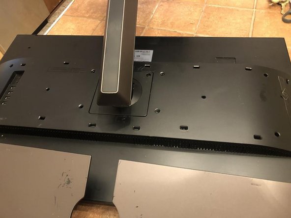
    • Here is the Samsung monitor LS32D85K sold as SD850

    • fairly clean and sleek design without frills

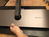
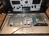
    • This one has a broken LCD as well but needed to check the power supply. Monitor powers on = power supply working

  2. Samsung LS32D85KTSR Power Supply Replacement: step 2, image 1 of 3 Samsung LS32D85KTSR Power Supply Replacement: step 2, image 2 of 3 Samsung LS32D85KTSR Power Supply Replacement: step 2, image 3 of 3
    • First is the removal of the plastic that covers the midsection of the back cover. Simply pull straight up on the midsection.

    • Continue to move along one side

    • until the end to release the snaps. No tools needed

  3. Samsung LS32D85KTSR Power Supply Replacement: step 3, image 1 of 3 Samsung LS32D85KTSR Power Supply Replacement: step 3, image 2 of 3 Samsung LS32D85KTSR Power Supply Replacement: step 3, image 3 of 3
    • Lastly unsnap the opposite side

    • Remove the cover to gain access to the stand.

    • The stand is fastened to the monitor by two (2) Philips head screws. Remove those

  4. Samsung LS32D85KTSR Power Supply Replacement: step 4, image 1 of 3 Samsung LS32D85KTSR Power Supply Replacement: step 4, image 2 of 3 Samsung LS32D85KTSR Power Supply Replacement: step 4, image 3 of 3
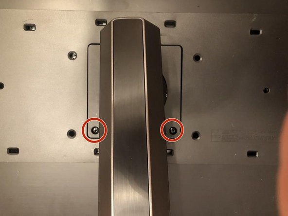
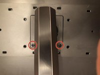
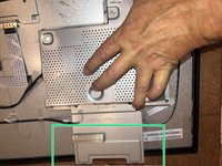
    • With the screws removed, tilt the with the screw holes up

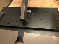
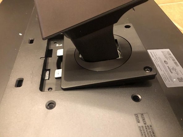
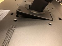
    • now pull the stand back to release the two metal tabs to remove the stand.

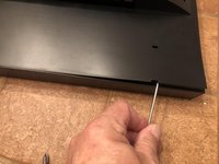
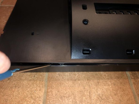
    • On the top left corner of the back cover is a small release opening to insert either a plastic removal tool or similar. Here a flathead screwdriver was used. Insert it and gently lift it to release the first tab

  5. Samsung LS32D85KTSR Power Supply Replacement: step 5, image 1 of 3 Samsung LS32D85KTSR Power Supply Replacement: step 5, image 2 of 3 Samsung LS32D85KTSR Power Supply Replacement: step 5, image 3 of 3
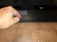
    • move the tool along the top line to release more tabs all the way to the end

    • and finally along the sides. As the tool moves along the holding tabs will unsnap. Some areas required more of a lever action to release them. NO great force needed for this

    • Once all the tabs release the back will simply come off.

  6. Samsung LS32D85KTSR Power Supply Replacement: step 6, image 1 of 3 Samsung LS32D85KTSR Power Supply Replacement: step 6, image 2 of 3 Samsung LS32D85KTSR Power Supply Replacement: step 6, image 3 of 3
    • Lift the back cover of and out of the way will reveal the boards

    • Power board

    • Main board

    • T-Con board

    • On the top of the power board are two flat ribbon cables. Those are the backlight cables which need to be removed.

  7. Samsung LS32D85KTSR Power Supply Replacement: step 7, image 1 of 3 Samsung LS32D85KTSR Power Supply Replacement: step 7, image 2 of 3 Samsung LS32D85KTSR Power Supply Replacement: step 7, image 3 of 3
    • Removal of the left cable by simply pulling on the white connector (never the cable)

    • Next remove the right backlight cable

    • On the side of the power board is a connector labeled with the number 10. The is the connection between the main board and the power board. Remove that cable

  8. Samsung LS32D85KTSR Power Supply Replacement: step 8, image 1 of 3 Samsung LS32D85KTSR Power Supply Replacement: step 8, image 2 of 3 Samsung LS32D85KTSR Power Supply Replacement: step 8, image 3 of 3
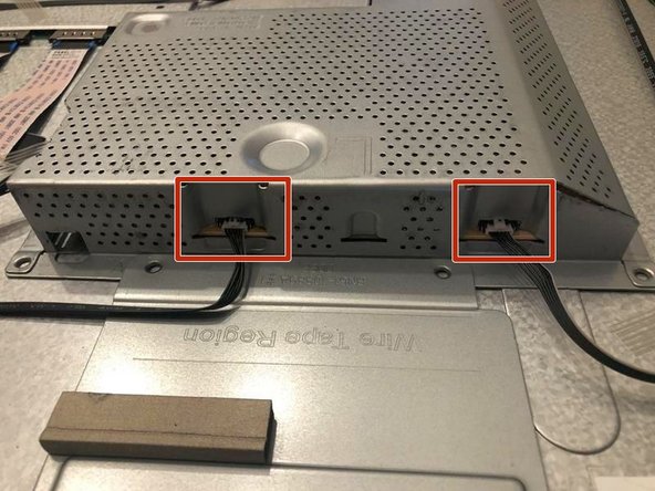
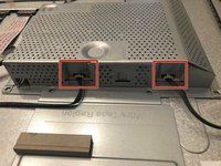
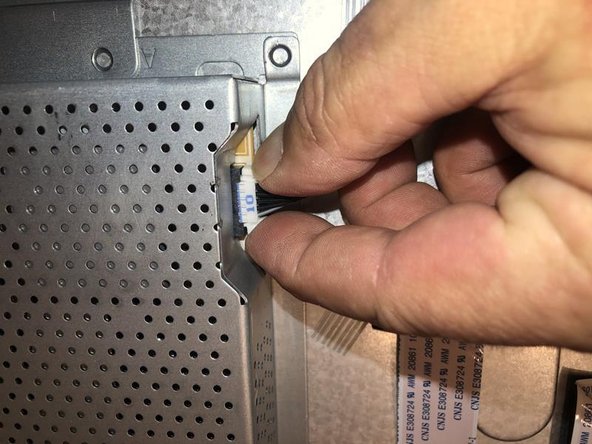
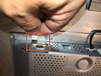
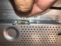
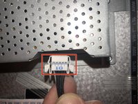
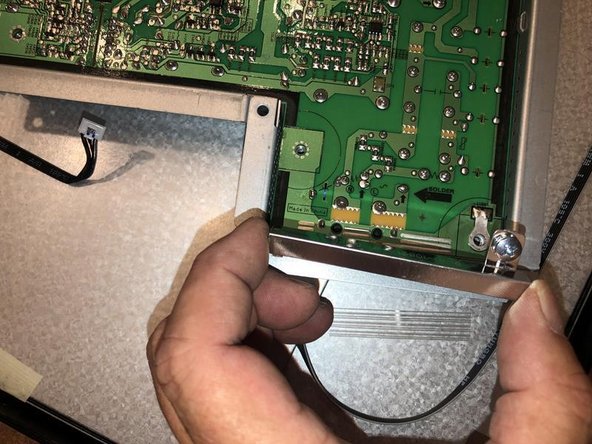
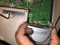
    • To release the cable from the connector, simply squeezing the two tabs on the side and a gentle pull on the connector will release the cable.

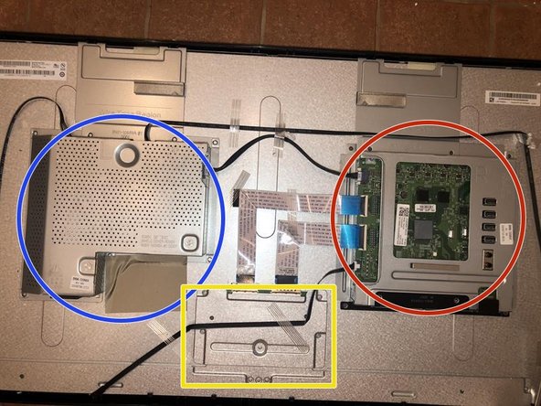
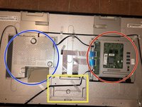
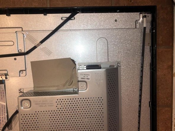
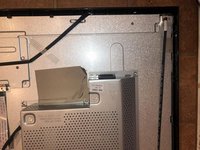
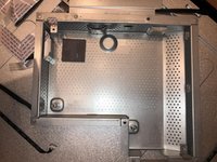
    • Interestingly enough the power board holder does not use any fasteners on the chassis etc. It is simply held in place by some adhesive strip.

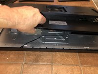
    • Pulling the adhesive strip off and sliding the power board holder of the lip of the monitor, allows its removal.

  9. Samsung LS32D85KTSR Power Supply Replacement: step 9, image 1 of 3 Samsung LS32D85KTSR Power Supply Replacement: step 9, image 2 of 3 Samsung LS32D85KTSR Power Supply Replacement: step 9, image 3 of 3
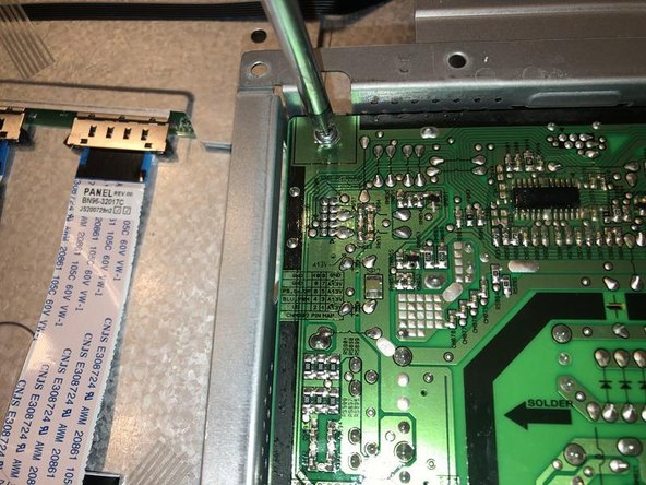
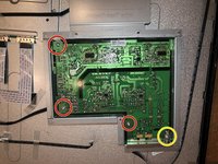
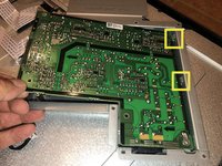
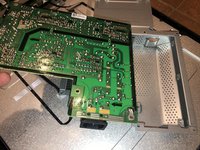
    • Turn the power board loder over to get a good visual of the board. It is fastened with four (4) Philips head screws.

    • One (1) of the screws appears to hold the ground trap in place as well

    • Remove the three (3) screws first

    • Then remove the Philips head screw that holds the board and the ground strap in place

  10. Samsung LS32D85KTSR Power Supply Replacement: step 10, image 1 of 3 Samsung LS32D85KTSR Power Supply Replacement: step 10, image 2 of 3 Samsung LS32D85KTSR Power Supply Replacement: step 10, image 3 of 3
    • With all the screws removed angle teh board so as to free the two metal tabs on the side of the holder

    • Pull the board to the side and remove it

    • Here is the holder with what appears to be either a thermal pad or insulation pad.

  11. Samsung LS32D85KTSR Power Supply Replacement: step 11, image 1 of 3 Samsung LS32D85KTSR Power Supply Replacement: step 11, image 2 of 3 Samsung LS32D85KTSR Power Supply Replacement: step 11, image 3 of 3
    • Turn the board over to visualize the component part side.

    • Whenever one works on a power supply one must remember not to touch the components since the capacitors may still be charged and could cause fatal electrical shocks. Discharge the capacitors before working on the board.

    • There is a reason for all that goop. That is the MOSFET that appears to be the Achilles Heal of the power board.

    • That is a KF12N60 N CHANNEL MOS FIELD EFFECT TRANSISTOR.

Conclusion

To reassemble your device, follow these instructions in reverse order.

5 other people completed this guide.

oldturkey03

Member since: 09/29/10

778,207 Reputation

118 Guides authored

Team

Global Fixers Member of Global Fixers

Community

31 Members

520 Guides authored

4 Comments

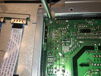
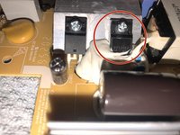
If someone wants to fix this PSU, most of them have the same fault: The 6.3A fuse blows because the PFC chopper FET dies. To fix it: remove the **11N60 FET from the left side of the angled heatsink, under the silicone.

Replace it with ang 11N60 FET, that has at least 600V Ugs voltage, 33W power dissipation and less than 0.55ohm RDSon. Replace the fuse too, and now you have a fixed the PSU for under $5.

(The spc7011f PFC IC usually doesn't get damaged, because the gate has a 22V zener diode tied to ground.)

If you can't desolder the FET in one piece, cut off the legs and remove them one by one.

Do not attempt to fix the PSU, if you are not familiar with fixing mains powered devices.

Máté Szűcs - Reply

hello, can you give me more info on the fuse?

Hans - Reply

also this one...

FQPF11N60C FET 11N60C MOSFET 600V

or this one

FCP11N60N TO-220 600V 10.8A N-channel FET

thanks in advance

Hans - Reply

or this one

SPA11N60C3 N-FET 650V 11A 33W TO220F

:)

Hans - Reply

Add Comment

View Statistics:

Past 24 Hours: 0

Past 7 Days: 14

Past 30 Days: 68

All Time: 2,723