
Samsung BD-F5900 Main Logic Board Replacement

What you need

  1. Samsung BD-F5900 Main Logic Board Replacement, Top Cover: step 1, image 1 of 1
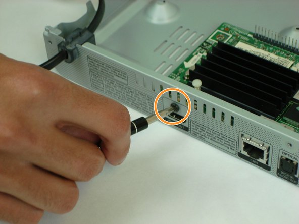
    • Using a #1 Phillips head screwdriver, remove the three 10mm screws on the back panel.

    • Tilt the back of the top cover forward to remove from chassis.

  2. Samsung BD-F5900 Main Logic Board Replacement: step 2, image 1 of 1
    • Gently pull up on the ribbon cable by the blue tab to remove it from the power supply board.

  3. Samsung BD-F5900 Main Logic Board Replacement, Power Supply: step 3, image 1 of 2 Samsung BD-F5900 Main Logic Board Replacement, Power Supply: step 3, image 2 of 2
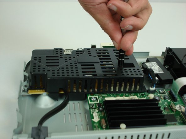
    • Using a #1 Phillips head screwdriver, remove the two 7.5mm screws on top of the plastic cover and remove the cover.

  4. Samsung BD-F5900 Main Logic Board Replacement: step 4, image 1 of 1
    • Press down on the plastic retaining clip and pull backwards to remove the AC power connector from the power supply board.

  5. Samsung BD-F5900 Main Logic Board Replacement: step 5, image 1 of 3 Samsung BD-F5900 Main Logic Board Replacement: step 5, image 2 of 3 Samsung BD-F5900 Main Logic Board Replacement: step 5, image 3 of 3
    • Using the plastic spudger tool, gently pry on either side of main power connector (CON801) to disconnect from main logic board.

    • Pry a little bit on each side of board until the board lifts away.

    • Tilt the board forward and lift up to remove from the chassis.

  6. Samsung BD-F5900 Main Logic Board Replacement, Main Logic Board: step 6, image 1 of 1
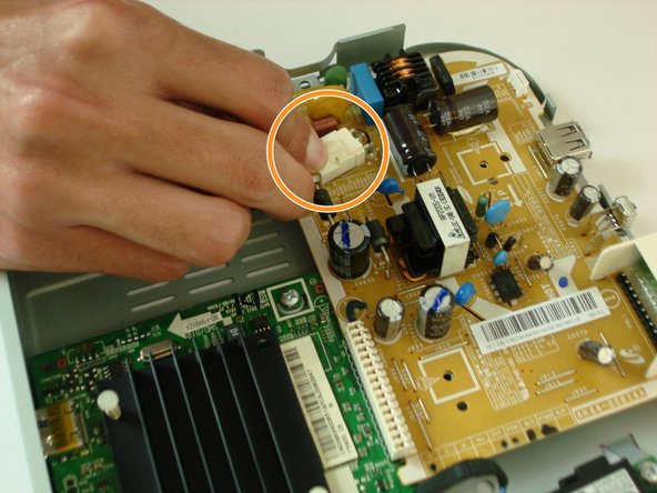
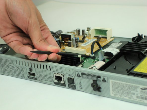
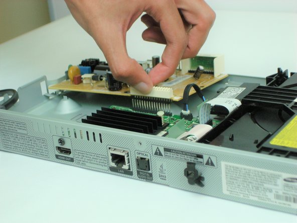
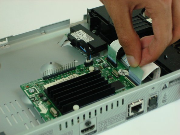
    • Remove the two ribbon cables from the Main Logic Board assembly by gently pulling up on the blue tab.

    • Be careful not to damage the ribbon cable by using too much force.

  7. Samsung BD-F5900 Main Logic Board Replacement: step 7, image 1 of 1
    • Disconnect the WiFi board cable connector

  8. Samsung BD-F5900 Main Logic Board Replacement: step 8, image 1 of 2 Samsung BD-F5900 Main Logic Board Replacement: step 8, image 2 of 2
    • Using a #1 Phillips head screwdriver, remove the three 7.5 mm screws from the board

    • Also remove the 10 mm screw from the rear panel.

    • Remove the Main Logic Board

Conclusion

To reassemble your device, follow these instructions in reverse order.

Louis McKean

Member since: 10/18/17

528 Reputation

5 Guides authored

Team

USF Tampa, Team S1-G21, Cagle Fall 2017 Member of USF Tampa, Team S1-G21, Cagle Fall 2017

USFT-CAGLE-F17S1G21

3 Members

5 Guides authored

0 Comments

Add Comment

View Statistics:

Past 24 Hours: 0

Past 7 Days: 4

Past 30 Days: 9

All Time: 389