What you need
-
-
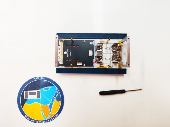
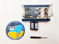
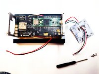
The kit contains:
-
8 Boards: Main Board, Power Board, Front Board, Back Board, Left Board, Right Board, RPI Board and Payload Board.
-
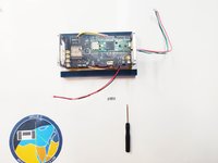
2 Antennas: 433MHz Dipole antenna and 2.4GHz Dipole antenna.
-
2 Frames: The frame with the 3/4 circle cut is the front side and the other frame is the back side.
-
13 Cables: 7 with two wires, 5 with four wires and 1 RPI Camera ribbon cable
-
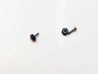
42 Bolts and Spacers: 28 M2x5mm bolts, 2 M2x12mm bolts, 4 female to female long spacers, 2 female to female short spacers, 4 female to male short spacers.
-
Outers: 1 GPS, 2 NTC's and 1 phillips screwdriver
-
-
-
First of all start with the Power Board assembly, in the first step, you need 4 M2x5mm bolts (two for each side), 2 frames, and a Phillips screwdriver.
-
Assemble the frame to Power Board using the M2x5mm bolts and don't tighten the bolts all the way yet. Please note the frame holes aren't symmetrical, on each frame piece there has an arrow mark the arrow points to the top of the satellite, the frame with the 3/4 circle cut is supposed to go where the "Z+"
-
Now take 4 M2x5mm bolts, 2 female to female short spacers, and 2 female to male shot spacers. assemble the spacers as shown in the third image.
-
-
-
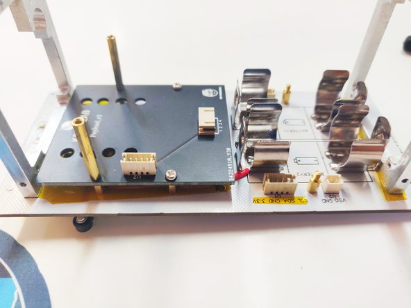
Take 2 M2x5mm bolts and 2 female to female long spacers.
-
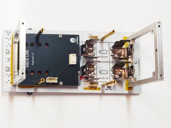
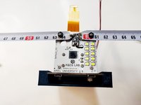
Place the Payload Board where the "KC&G LAB" logo is facing upward and pointing to the frame with the 3/4 circle cut.
-
Screw the M2x5 bolts to the right side holes of the Payload Board.
-
Screw the female to female long spacers to the left side of the Payload Board.
-
Take another 2 M2x5mm bolts, 2 female to female long spacers and 2 female to male short spacers.
-
On the middle of the battery holder on each side screw, the first bolt and a short female to male spacer then screw on the top of the short spacer the long female to a female spacer
-
-
-
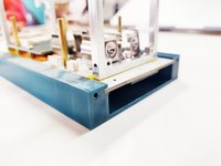
Before inserting the batteries, there is a crucial step. There are two micro switches, each microswitch control different power paths, Battery power path, and Solar power path.
-
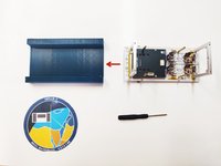
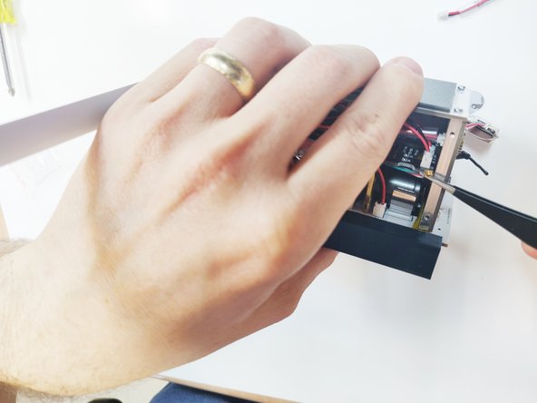
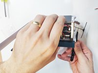
For safety reasons after assembling the Power Board and the Payload Board, you need to insert the Power Board with the Payload Board facing toward the POD
-
-
-
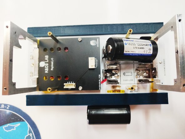
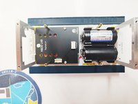
Before inserting the batterie's note the polarity of the battery, on the battery holder, there is a drawing that shows the right polarity.
-
Now cautiously insert one battery each time.
-
NOTE: Please use protected cell, the battery holder is designed to fit a protected cell { (D)18.3* (L) 38.8mm (±0.2mm) }
-
-
Tool used on this step:Tweezers$4.99
-
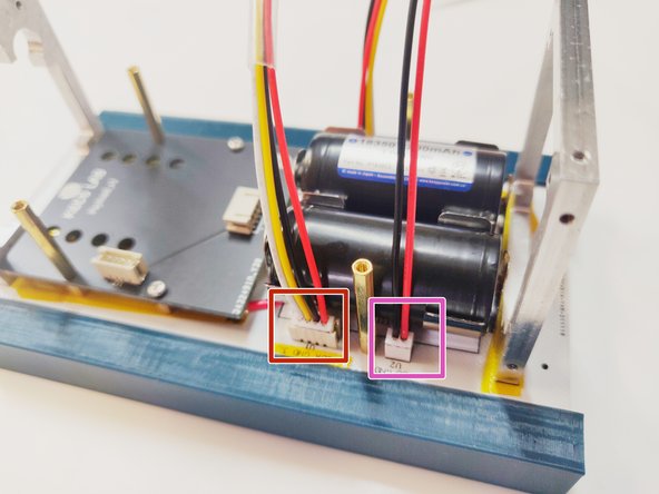
In this part you need, 3 cables:
-
PM-1, PM-2 and SOLAR *no matter the number. NOTE: the polarity of the cables isn't relevant, recommended to use tweezers
-
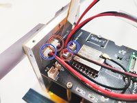
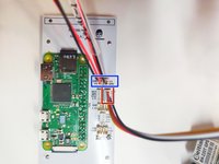
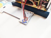
Connect the PM-1 cable to the marked red square JST housing.
-
Connect the PM-2 cable to the marked blue square JST housing.
-
Connect the SOLAR cable to the marked pink square JST housing.
-
-
-
-
Connect PM-1 cable to the marked red square JST housing.
-
Connect PM-2 cable to the marked blue square JST housing.
-
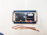
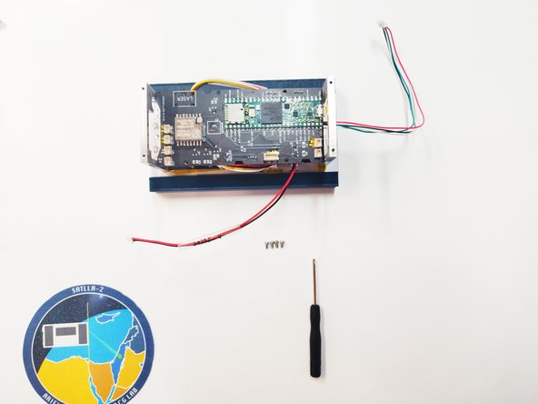
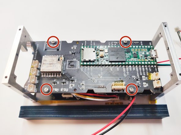
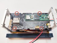
Insert the main board on top of the spacers, use 4 M2x5mm bolts and phillips screwdriver to tight the Main Board to the spacers.
-
-
-
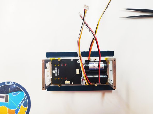
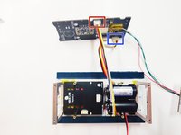
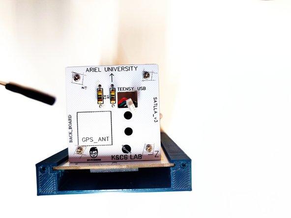
Take the 4 wire GPS cable that connected to the Main Board, and insert to the square cut on the Back Board with the writing "TEENSY_USB".
-
Take 4 M2x5mm bolts and with phillips screwdriver tight the Back Board to the frame. NOTE: (don't over tight).
-
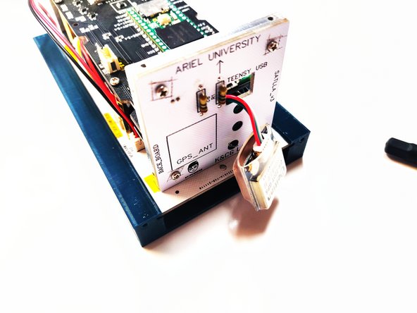
Connect the GPS to the 4 wire JST connector.
-
-
-
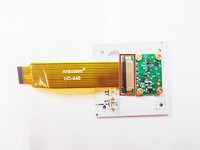
Take the RPI Camera ribbon cable and connect it to the camera fitted on the back of the Front Board. NOTE: work with tweezers and cautiously connect the ribbon cable to the camera.
-
Cautiously insert the Front Board into the frame, be careful not to damage the ribbon cable while inserting the Front Board.
-
Take 2 M2x5mm bolts and tight the lower right and left bolts. NOTE: (don't over tight).
-
-
-
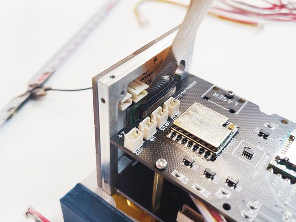
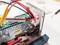
Take the 433MHz antenna cable and insert to the only hole in the Front Board.
-
With a tweezers cautiously pull the cable inside.
-
Cautiously connect the antenna cable to the SX1278 chip's IPEX connector.
-
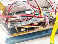
Connect MF-1 cable to the marked red square JST housing.
-
Connect MF-2 cable to the marked blue square JST housing.
-
-
-
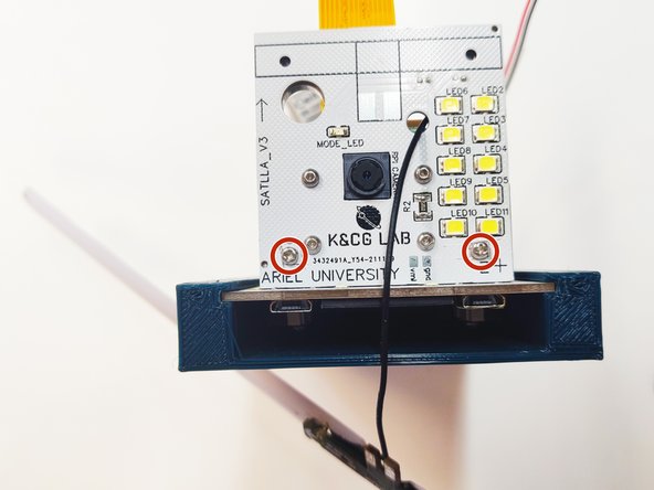
Take 2 M2x12mm bolts and 2 plastic spacers.
-
Tight the antenna to the Front Board as shown in the image.
-
-
-
Connect MF-1 cable to the marked red circle JST housing.
-
Connect MF-2 cable to the marked blue circle JST housing.
-
Connect MB-1 cable to the marked pink circle JST housing.
-
Connect NTC cable to the marked yellow circle JST housing. NOTE: there is no polarity on the NTC's.
-
-
-
Place the Right Board on the right side of the satellite. NOTE: the right side is where the "TEENSY_USB" square cut on the Back Board is close to.
-
Take 4 M2x5mm bolts and with a Phillips screwdriver tight all 4 bolts. NOTE: (don't over tight).
-
-
-
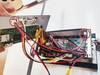
Connect RPI-M cable to the marked red square JST housing.
-
Connect 2 SOLAR cable's to the marked blue square JST housing.
-
On the Main Board connect the other side of the RPI-M cable to the pink square.
-
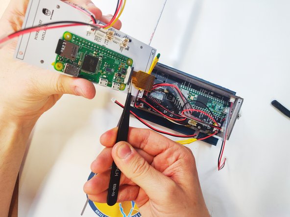
Cautiously connect the ribbon cable to the RPI camera socket. NOTE: the socket is fragile.
-
-
-
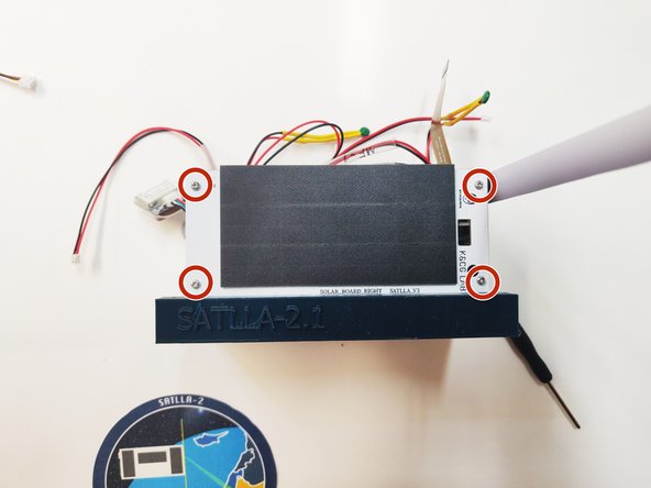
Connect one of the SOLAR cable's to the marked circle JST housing.
-
Take 4 M2x5mm bolts and with a Phillips screwdriver tight all 4 bolts. NOTE: (don't over tight).
-
-
-
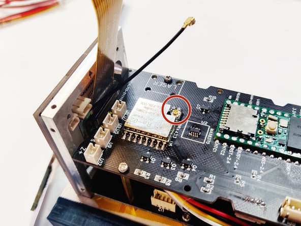
Insert the 2.4GHz antenna cable into the top hole of the Back Board.
-
With tweezers grab the end of the cable and pull it towards you.
-
Cautiously connect the antenna cable to the IPEX connector of the SX1280 Chip that market in a red circle.
-
-
-
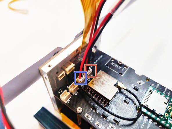
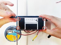
Connect the last SOLAR cable of the RPI Board to the marked blue square JST housing.
-
Connect the SOLAR cable of the Power Board to the marked red square JST housing.
-
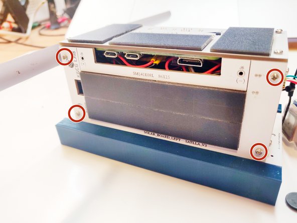
Take 4 M2x5mm bolts and with a Phillips screwdriver tight all 4 bolts. NOTE: (don't over tight).
-


To disassemble your device, follow these instructions in reverse order.
Cancel: I did not complete this guide.
One other person completed this guide.
