Introduction
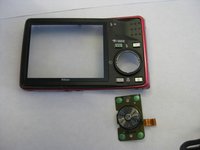
This guide is for the removal or installation of the rotary multi selector wheel.
What you need
-
-
Unscrew the two 3.5mm Phillips screws from the side with the AV outlet.
-
Unscrew the 3.5mm Phillips screw from the opposite side of the camera.
-
Unscrew the six 3.5mm Phillips screws from the bottom of the camera.
 Ask FixBot
-
-
-
Tool used on this step:Tweezers$4.99
-
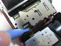
Place the plastic opening tool underneath the ribbon tab as shown. Gently lift the tab up.
-
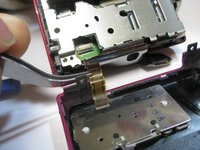
Gently pull the ribbon from the logic board with tweezers.
-
With the ribbon disconnected, the back casing should now be detached from the rest of the camera.
-
-
Tool used on this step:Tweezers$4.99
-
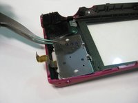
Lift up the metal cover and its button slowly using the tweezers.
-


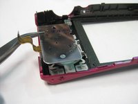
To reassemble your device, follow these instructions in reverse order.
Team

Cal Poly, Team 8-56, Johann Spring 2013 Member of Cal Poly, Team 8-56, Johann Spring 2013
CPSU-JOHANN-S13S8G56
4 Members
18 Guides authored