Introduction
This guide shows you how to replace a faulty spindle lock assembly. The symptoms of a faulty or clogged spindle lock assembly are failure to stop blade rotation in less than one full rotation, or if the spindle lock does not allow the blade to rotate freely when released (binding). For more information check our troubleshooting guide. Before getting started, remove the inner flange bushing, cut depth lever, and upper housing by following the Inner Flange Bushing Guide and steps 1-5 in the Switch Assembly Guide.
What you need
-
-
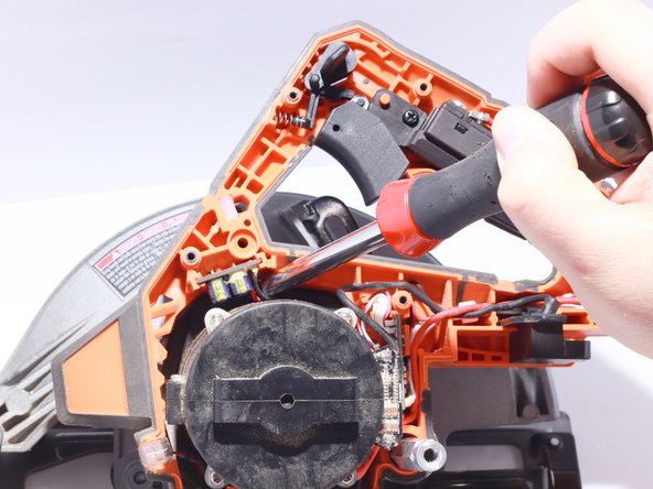
Remove the supplied Allen wrench from it's nesting space in the front of the handle.
-
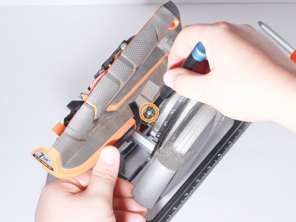
Remove one 7mm T20 torx screw to remove cut depth lever located behind the motor shroud on the left side of the saw.
-
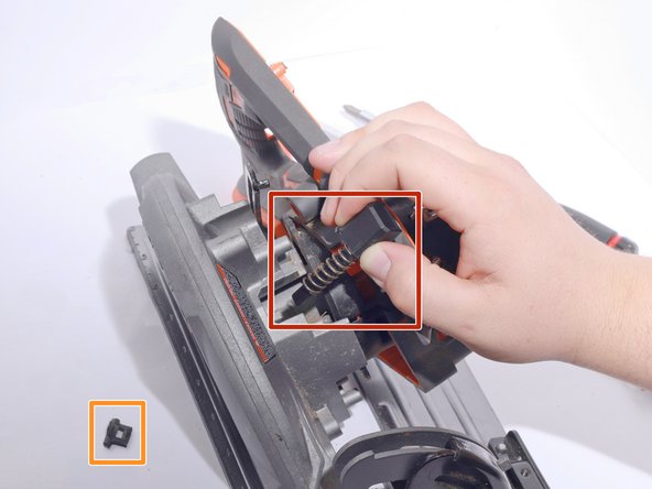
Slowly remove lever from saw ensuring not to lose the compression spring between the lever and retaining screw.
-
-
-
-
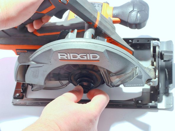
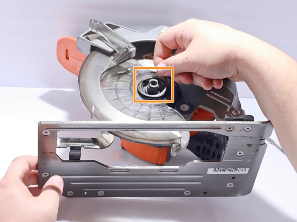
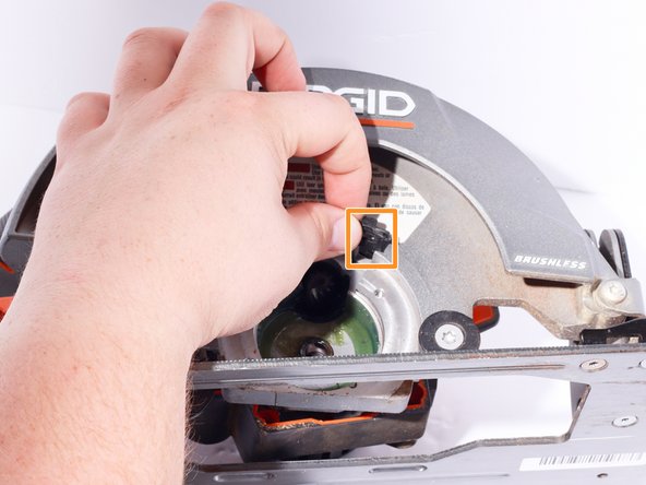
Depress and hold the spindle lock button located between the handle and blade shroud.
-
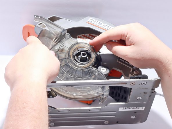
Using the supplied 6mm Allen Wrench that was removed while taking off upper housing, unscrew the bolt holding the outer flange, blade (if installed), and inner flange.
-
-
-
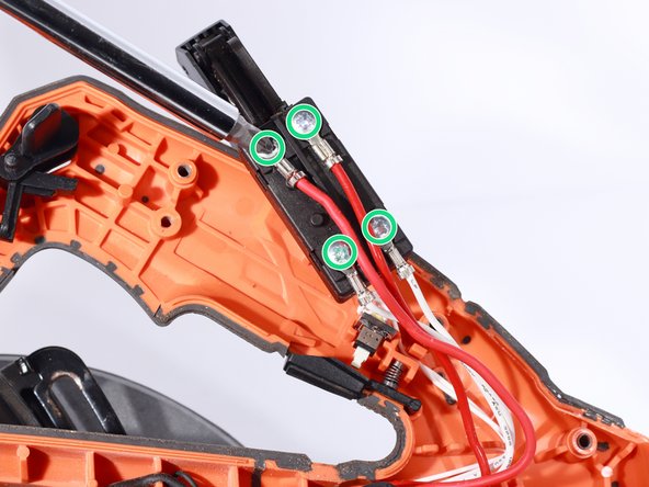
Remove the Torx T20 12mm screw located in the lower right corner of the gear box
-
Remove the Torx T20 12mm screw located in the upper left corner of the gear box
-
Remove the Torx T20 12mm screw located in the upper right corner of the gear box
-
Remove the Torx T20 12mm screw located in the lower left corner of the gear box
-
Remove the gear box assembly.
-
-
-
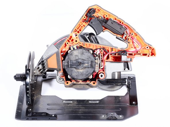
Loosen five 10mm Torx T10 Safety screws located around the motor casing to allow both halves of the motor casing to separate slightly.
-
Pulling the lower housing away from the metal blade shroud to access the last Torx T10 Safety screw in the motor casing. It is found near the hexagonal rod at the back of the handle.
-
-
-
With both halves of the motor casing loose, pull the motor housing away from the saw. The motor housing does not need to be fully removed, just moved enough to allow for clearance of the Spindle Lock Assembly.
-
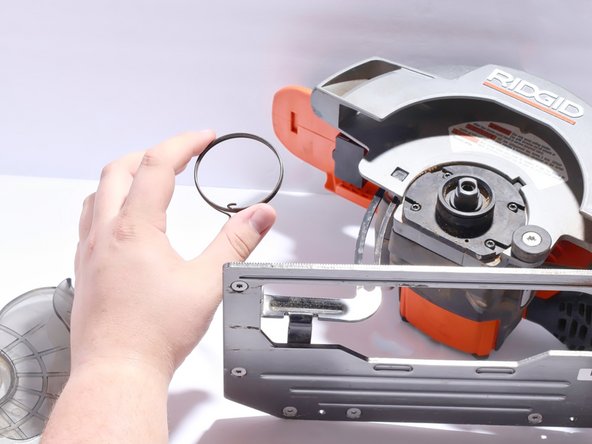
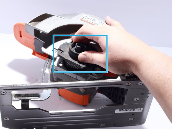
Remove the Spindle Lock Assembly by tilting the blade lock button away from the metal blade shroud and lifting it out of its channel.
-
Keep track of the rubber Dust Cover when removing the Spindle Lock Assembly.
-
Inspect the metal linkage for damage below the spring end. Replace it if necessary.
-
Inspect the Spindle Lock Assembly channel for sawdust or other debris which may prevent freedom of motion. Clear away any debris in the channel and lubricate with a graphite based lubricant.
-


To reassemble your device, follow these instructions in reverse order.
To reassemble your device, follow these instructions in reverse order.
Cancel: I did not complete this guide.
2 other people completed this guide.

Team

Embry-Riddle Aeronautical University, Team S1-G2, Watkins Fall 2019 Member of Embry-Riddle Aeronautical University, Team S1-G2, Watkins Fall 2019
ERAU-WATKINS-F19S1G2
4 Members
5 Guides authored