Introduction
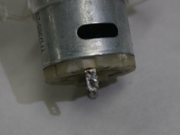
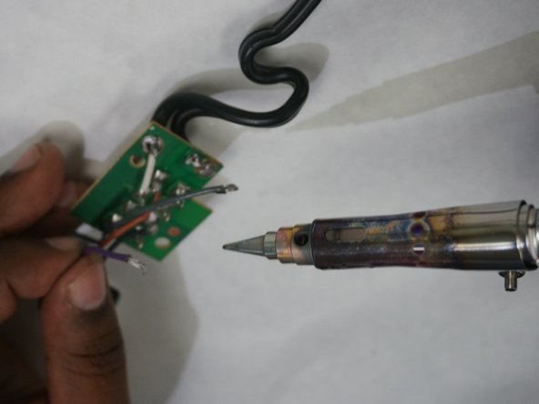
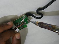
Sometimes there could be a weak section of a hair dryer's heating element and it could break at that point, at which time the heating element assembly, make sure to direct the force of the point of the soldering iron in a way as it will not slip and stab your support hand. If you do not know how to solder, here is a useful link: How To Solder and Desolder Connections
What you need
-
-
Using a Phillips #3 screwdriver, remove the single 25 mm Phillips head screw in the handle by turning it counterclockwise.
-
-
-
-
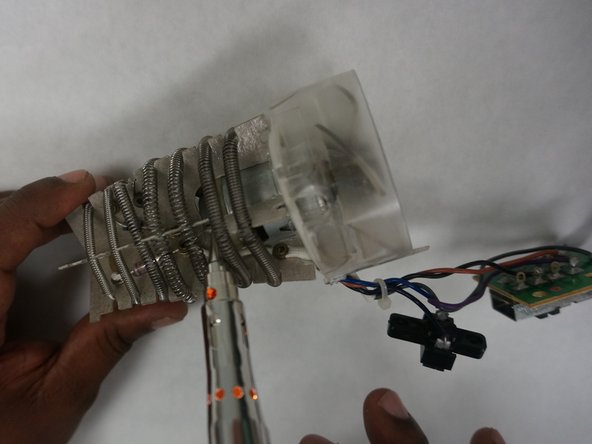
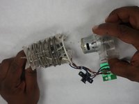
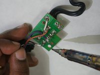
The fan/motor assembly is connected to the heating element assembly at two points need to be desoldered. After pulling the attached wires through the holes the fan/motor assembly will be free from the heating element assembly. Congratulations you have now completely removed the fan/motor assembly from this hair dryer!
-
-
-
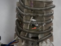
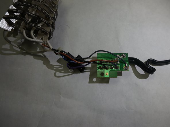
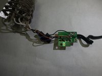
Once the fan/motor assembly is disconnected from the heating element assembly you will see that the heating element assembly is connected to a circuit board by four wires. The color of these wires are grey, black, purple and brown.
-


To reassemble your device, follow these instructions in reverse order.
Team

IUPUI, Team S2-G2, Wilson Summer 2018 Member of IUPUI, Team S2-G2, Wilson Summer 2018
IUPUI-WILSON-SU18S2G2
4 Members
4 Guides authored