Free Shipping on Domestic Orders $75+

Retro-Bit Retro Duo Circuit Board Replacement

What you need

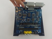
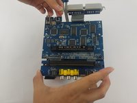
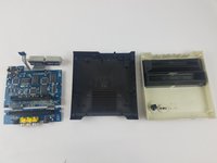
  1. Retro-Bit Retro Duo Circuit Board Replacement, Circuit Board: step 1, image 1 of 3 Retro-Bit Retro Duo Circuit Board Replacement, Circuit Board: step 1, image 2 of 3 Retro-Bit Retro Duo Circuit Board Replacement, Circuit Board: step 1, image 3 of 3
    • With the console on its top, remove the four 12 mm Phillips #2 screws.

    • There may be a sticker covering one or more of the screws. Simply remove the sticker before screw removal.

    • Flip the console on its feet. Carefully lift the top casing from the back (where the AV/S and power ports are).

    • To avoid damage, do not remove the top casing completely. There is a small LED circuit board connected to the main circuit board.

    Ask FixBot
  2. Retro-Bit Retro Duo Circuit Board Replacement: step 2, image 1 of 3 Retro-Bit Retro Duo Circuit Board Replacement: step 2, image 2 of 3 Retro-Bit Retro Duo Circuit Board Replacement: step 2, image 3 of 3
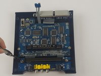
    • Remove the one 6 mm Phillips #0 LED circuit board screw.

    • Lift the top case and set aside.

    Ask FixBot
  3. Retro-Bit Retro Duo Circuit Board Replacement: step 3, image 1 of 3 Retro-Bit Retro Duo Circuit Board Replacement: step 3, image 2 of 3 Retro-Bit Retro Duo Circuit Board Replacement: step 3, image 3 of 3
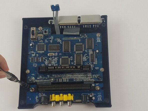
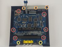
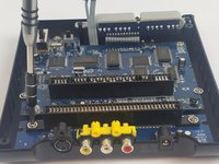
    • Remove the 11 screws holding the circuit boards and ports in place.

    • Six 11 mm Phillips #2 holding the circuit boards.

    • Three 12 mm Phillips #2 screws holding the controller ports.

    • Two 7 mm Philllips #2 screws holding the back ports

    Ask FixBot
  4. Retro-Bit Retro Duo Circuit Board Replacement: step 4, image 1 of 3 Retro-Bit Retro Duo Circuit Board Replacement: step 4, image 2 of 3 Retro-Bit Retro Duo Circuit Board Replacement: step 4, image 3 of 3
    • Carefully lift the circuit board while holding either the AV or controller ports. Alternatively, you can hold the circuit board on its edges.

    • Make sure to lift the circuit board completely out of the bottom case.

    • To avoid damage, do not to touch the top or bottom faces of the circuit board.

    Ask FixBot
Conclusion

To reassemble your device, follow these instructions in reverse order.
Truong Vo

Member since: 09/25/17

324 Reputation

3 Guides authored

Team

USF Tampa, Team S4-G4, Eyestone Fall 2017 Member of USF Tampa, Team S4-G4, Eyestone Fall 2017

USFT-EYESTONE-F17S4G4

3 Members

10 Guides authored

1 Guide Comment

I hope you show the second part were you replace the 72pin connector. Please include part source.

The 72 pin connector grabs too tightly on the cart.

Thanks.

George Tedrick - Reply Share

Add Comment

View Statistics:

Past 24 Hours: 4

Past 7 Days: 22

Past 30 Days: 101

All Time: 3,137