Introduction
This guide will show you how to remove the CCFL tubes from the CCFL assembly.
What you need
-
-
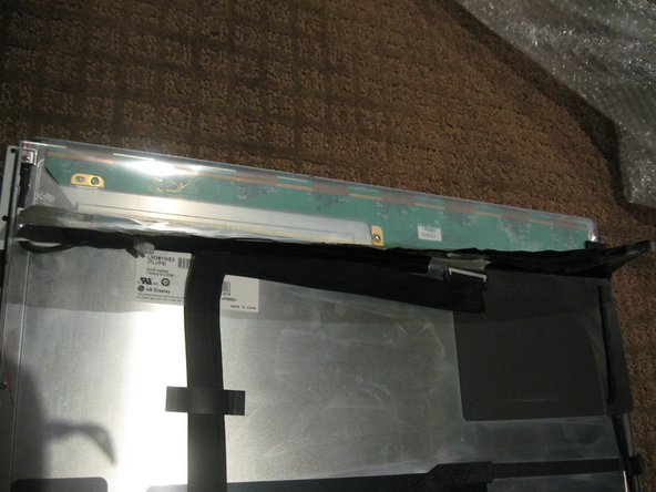
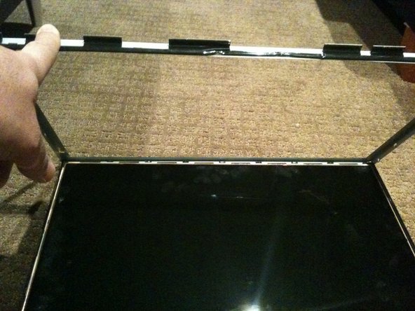
Once the LCD panel is removed you need to peel back the black foil from the top edge of the LCD to reveal the clear plastic PCB protector.
-
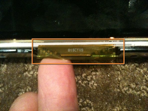
There are a total of 8 flex cables along the top edge
-
-
-
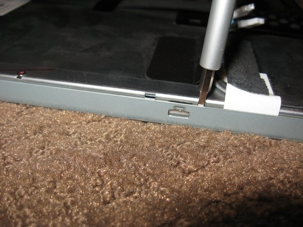
Stand the LCD panel on its TOP edge and locate the lock tabs along the BOTTOM edge. There are 5 along the length of the bottom edge
-
Use a flat blade driver or metal spudger to Gently pop the bezel off the lock tabs.
-
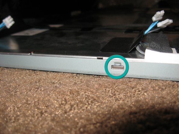
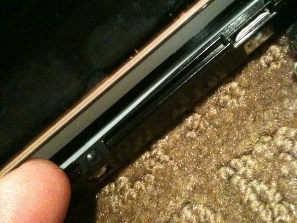
Locate the lock tabs on either side of the LCD panel. There are 2 on each side
-
Use a flat blade driver or metal spudger to Gently pop the bezel off the side lock tabs.
-
-
-
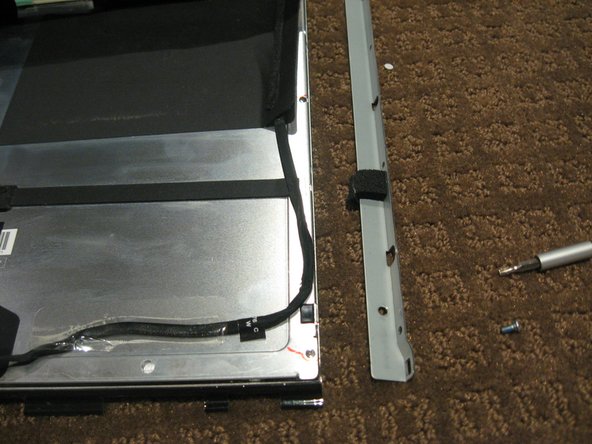
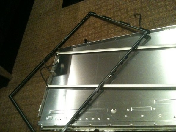
Now gently separate the metal bezel from the main body of the LCD panel
-
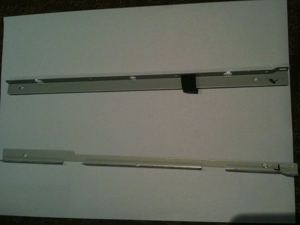
Lay the LCD panel down on with viewing side UP and remove the metal bezel
-
Note the 3 flex tabs on the left edge
-
-
-
Once the LCD is loose you need to HOLD it in place in the black plastic frame and GENTLY flip the entire assembly so the LCD is flat on the work surface
-
-
-
-
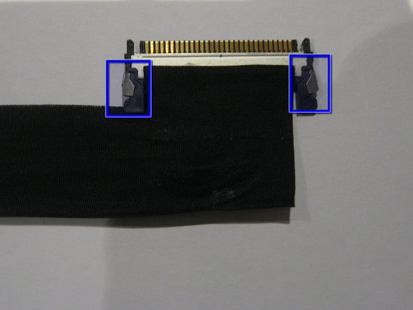
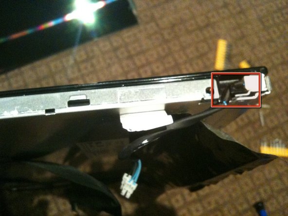
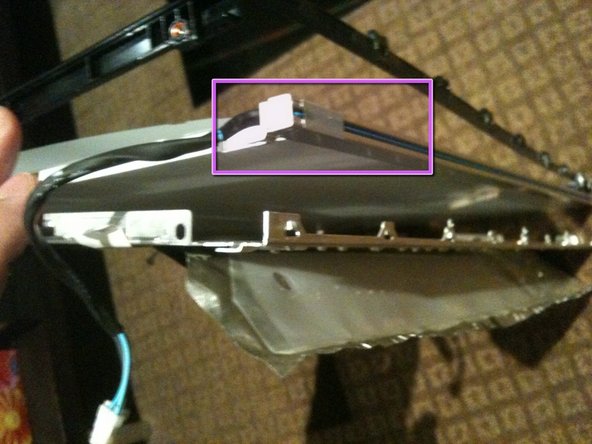
Remove the tape securing the LVDS cable
-
Press IN the 2 silver spring loaded catches on either side to release the cable and gently extract it from the connector
-
-
-
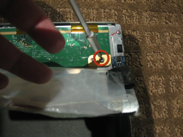
Peel the back Black foil and clear plastic PCB protector to fully expose the PCB that runs across the top of the LCD assembly
-
Remove the 2ea Philips head screws from each end of the PCB
-
-
-
Gently flip the PCB over 180deg so it is off the aluminum back panel.
-
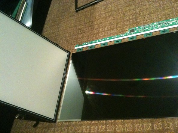
Now lift the the back panel off the LCD separating the LCD from the back light assembly
-
-
-
Remove the 6 Philips screws from the rear of the back light assembly
-
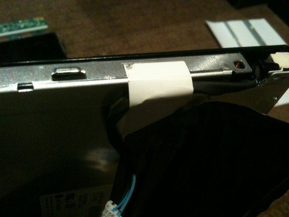
Removing the white tape from the CCFL cable.
-
Un-clip the CCFL cable from the black plastic surround
-
-
-
Separate the black plastic surround from the aluminum back plate to access the CCFL tube assemblies
-
Start by un-clipping the tabs along the top edge of the assembly. There are 4 tabs along the top
-
The top CCFL tube can be seen and CAREFULLY removed
-
-
-
The bottom of the black surround can now be un-clipped and the entire surround removed
-
There are 4 tabs along the bottom of the assembly
-
Once the black surround is off the rest pretty much comes apart with the bottom CCFL tube being able to be removed in a similar manner to the top
-
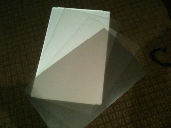
The centre of the back light assembly is made up of 4 main parts. A perspex sheet with white plastic coating, 2 opaque matt plastic sheets, and 1 Pearlescent matt plastic sheet
-
-
-
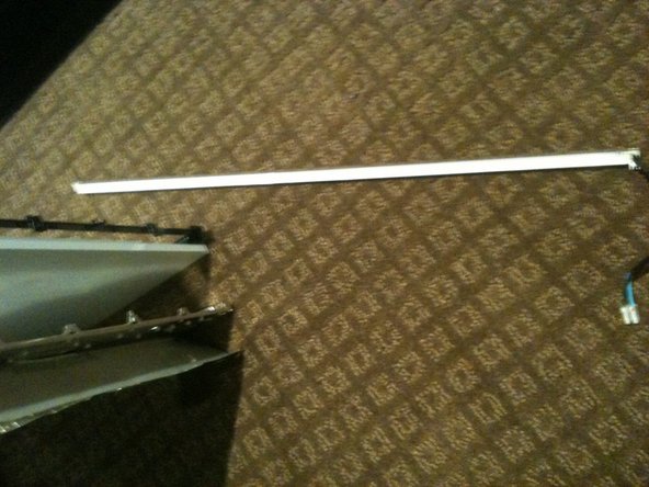
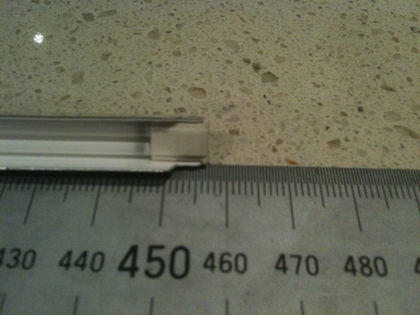
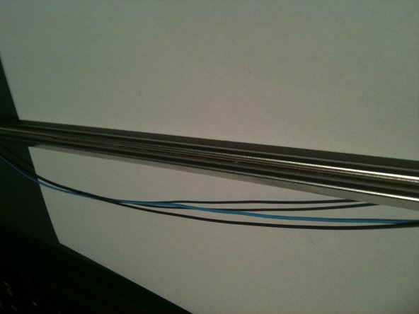
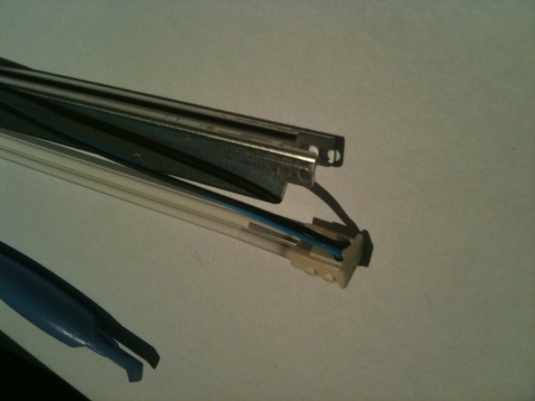
The CCLF tube assemblies are made up of a U shaped reflector with 2ea individual tubes inside. The entire assembly is 457mm long and 7.6mm wide. There are no part numbers on the assembly however there is a S on the end with the wires attached and an 18 on the other end.
-
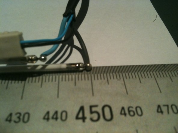
The individual tubes are 448mm long (excluding the terminals - standard way to measure is end of glass to end of glass) and are 2.4mm diameter.
-
-
-
Remove the white tape from either end of the rear of the CCFL assembly.
-
Carefully remove about 15-20mm of heat shrink from the CCFL cable to allow the end cap to be removed, making sure you DO NOT cut or nick the wire insulation.
-
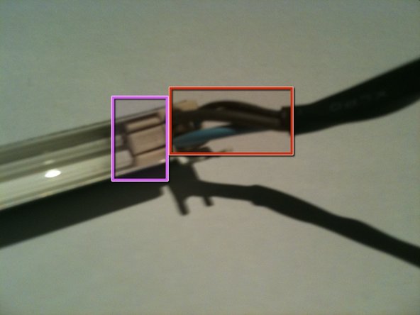
While holding the assembly, slowly and gently pull the THICK wires up and out of the slots in the white rubber cap.
-
This will reveal the pins and solder joints.
-
-
-
Gently push the THIN wires through the rubber end cap to create a bit of a loop on the rear of the assembly.
-
Using a plastic pry tool you can pop the rubber end cap out and then lift the thin wires out of the groove in the rear of the CCFL assembly
-
Run the pry tool the length of the assembly and free the wires all the way to the other end cap
-
gently pop the rubber end cap out of the assembly
-
-
-
Gently pull the rubber end cap off the CCFL to expose the pins and solder joints
-
Now its a simple task of un-soldering each wire and soldering in the new CCFL
-
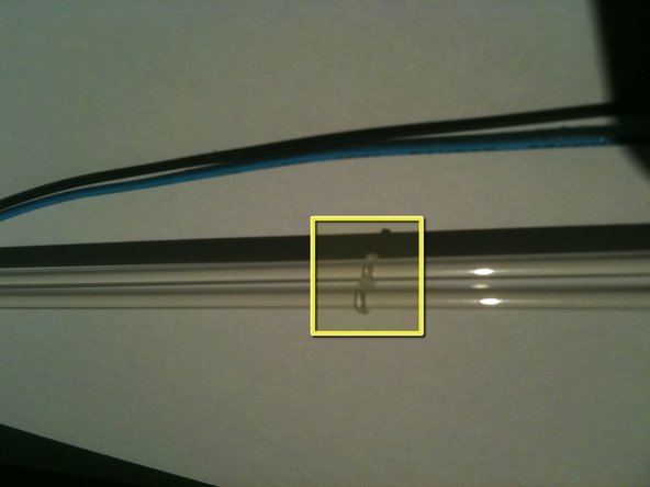
There is a little figure 8 rubber band tying the 2 CCFL together at their centre.
-


Team
