
Remove Outer Case

What you need

  1. Remove Outer Case, Prepare the Printer.: step 1, image 1 of 2 Remove Outer Case, Prepare the Printer.: step 1, image 2 of 2
    • Remove the printer from the optional second paper tray.

    • Pull out the paper tray from the front, and the duplexer from the rear.

    • Removing the print head (see the HP user guide) may also reduce the chance of ink leakage while working on the printer.

  2. Remove Outer Case, Control Panel: step 2, image 1 of 2 Remove Outer Case, Control Panel: step 2, image 2 of 2
    • Hold up the control panel with one hand, reach underneath it with the other, and pull firmly downward on the curved support to detach it from the display

    • Lifting the display further up, reach behind the brown plastic cover, and pull it forwards to release it

  3. Remove Outer Case, Control Panel: step 3, image 1 of 3 Remove Outer Case, Control Panel: step 3, image 2 of 3 Remove Outer Case, Control Panel: step 3, image 3 of 3
    • Rest the machine on it's rear panel, so you can access the cable.

    • Lift up the brown clamp, and pull out the cable

    • Using a T-10 Torx screwdriver, undo the two screws beneath the display (pictured)

    • The display remains attached to the scanner assembly for now. If you need to detach it from the scanner - for instance, to operate the printer while it is open - you can detach it once the scanner assembly is removed.

  4. Remove Outer Case, Left Side (Controller Board) Panel: step 4, image 1 of 3 Remove Outer Case, Left Side (Controller Board) Panel: step 4, image 2 of 3 Remove Outer Case, Left Side (Controller Board) Panel: step 4, image 3 of 3
    • On the back of the printer, remove the two screws on the right hand side (left-hand when viewed from the front.

    • Open the door on the front of the computer, and remove the one screw on the lower left-hand side.

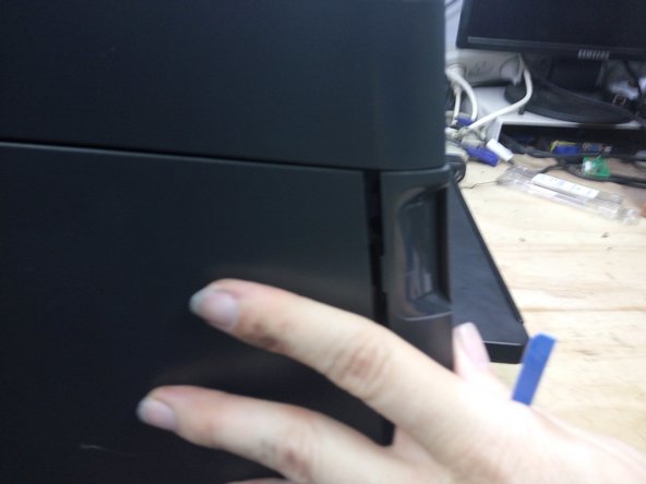
    • Using a spudger lever firmly outwards on the lower rear side of the panel.

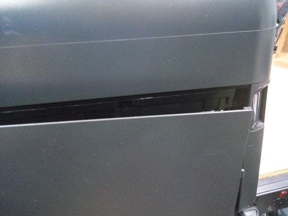
    • With your other hand, push the panel backwards, It will slide half a centimeter backwards and come free.

    • Could you help me? It would be useful if you could take an image of the rear of the printer, add it to this guide, so the locations of various screws can be marked.

  5. Remove Outer Case, Disconnect Cables: step 5, image 1 of 1
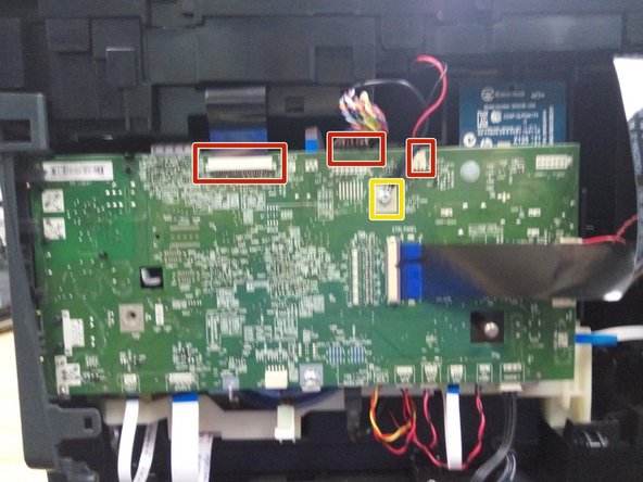
    • Disconnect the scanner flatfex, sheet feeder and LED cables (marked in red).

    • Remove the earth strap (marked in yellow).

    • No other cables need to be removed at this time.

  6. Remove Outer Case, Remove the scanner assembly: step 6, image 1 of 2 Remove Outer Case, Remove the scanner assembly: step 6, image 2 of 2
    • Remove the remaining screws around the top of the printer.

    • Lift the scanner assembly away from the printer.

    • If you need to detach the display, lay the scanner assembly upside down, lower the display assembly, push it to the right, and then adjust the angle of the display until it drops away from the scanner. Reconnect it to the flat-flex cable, and clip the support back into the rear to hold it. The printer will operate normally without the scanner.

  7. Remove Outer Case, Remove the output tray: step 7, image 1 of 3 Remove Outer Case, Remove the output tray: step 7, image 2 of 3 Remove Outer Case, Remove the output tray: step 7, image 3 of 3
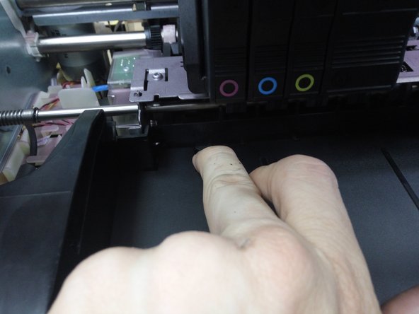
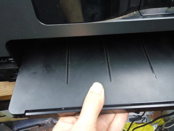
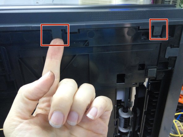
    • Depress the two clips at the rear of the output tray, and pull the tray forward.

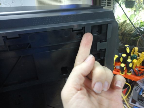
    • Rest the printer on its rear panel, depress the two clips under the tray, and slide the white support clear of the tray.

    • Pull the output tray clear.

  8. Remove Outer Case, Remove the right hand side panel.: step 8, image 1 of 1
    • Remove the single silver screw (pictured)

    • Remove the two screws from the rear left-hand side (right hand when viewed from the front)

  9. Remove Outer Case, Remove the Right-Hand Side Panel (cont.): step 9, image 1 of 3 Remove Outer Case, Remove the Right-Hand Side Panel (cont.): step 9, image 2 of 3 Remove Outer Case, Remove the Right-Hand Side Panel (cont.): step 9, image 3 of 3
    • Release the one clip on the inside front of the panel.

    • Release the two clips on the underside of the printer.

  10. Remove Outer Case, Remove the Right-Hand Side Panel (cont): step 10, image 1 of 2 Remove Outer Case, Remove the Right-Hand Side Panel (cont): step 10, image 2 of 2
    • Pull outwards on the front to release a hidden clip.

    • Rotate the panel outwards until the clips on the rear of the panel detach.

    • If the panel doesn't detach easily, it may help to remove the screws securing the back panel first.

  11. Remove Outer Case, Remove the rear panel: step 11, image 1 of 1
    • Remove the remaining screws on the rear of the printer.

    • Release the two clips on the underside of the printer.

    • Detach the rear panel.

  12. Remove Outer Case, Remove the power button cover: step 12, image 1 of 3 Remove Outer Case, Remove the power button cover: step 12, image 2 of 3 Remove Outer Case, Remove the power button cover: step 12, image 3 of 3
    • Using multple tools and considerable force, unclip the power button cover from the bottom.

    • Concentrate on the points marked with arrows. This is the location of the clips. Forcing a plastic spudger in at these points should release this cover.

    • Release trims in the left-hadn quater panel

    • There are clips on the side, underneath, and two from the top.

  13. Remove Outer Case, Detach the front door.: step 14, image 1 of 2 Remove Outer Case, Detach the front door.: step 14, image 2 of 2
    • Detach the NFC connector from the circuitboard, (Socket location marked in red) and pull the cable free from its restraints.

    • Bend the flexible flap attached to the front door upwards, then pull the studs free from the guides.

    • Pull the three hinges out of their clamps, and remove the front door.

  14. Remove Outer Case, Remove the Front Panel: step 15, image 1 of 3 Remove Outer Case, Remove the Front Panel: step 15, image 2 of 3 Remove Outer Case, Remove the Front Panel: step 15, image 3 of 3
    • Remove the power button, door sensor, and USB cables from the circuit board.

    • Slide back the catch on the Ctrl Panel socket, and remove the flat-flex.

    • Many repairs may not require this panel to be fully removed, so these cables may be left attached, if care is taken not to damage them.

    • Remove the 2 screws on the front left, and the one on the front right.

    • Release the clips in the paper output area

    • Release the two clips on the underside of the printer.

    • Pull the front panel free.

Conclusion

To reassemble your device, follow these instructions in reverse order.

One other person completed this guide.

Robert Backhaus

Member since: 11/10/12

1,000 Reputation

5 Guides authored

0 Comments

Add Comment

View Statistics:

Past 24 Hours: 0

Past 7 Days: 1

Past 30 Days: 11

All Time: 1,133