
Protocol Videodrone AP Camera Replacement

Karan Paranganat and 4 other contributors
Last updated on Jan 17, 2025
Views: 648
View statistics:
- Past 24 Hours:
- 4
- Past 7 Days:
- 17
- Past 30 Days:
- 74
- All Time:
- 648
Comments: 0
No one has left comments on this guide. Will you be first?
Go to guide commentsCompleted: 0 1
No one has marked this guide "completed." Will you be the first?
1 person has marked this guide "completed." It's you — great job!
Favorites: 0 1
No one has favorited (and subscribed to) this guide. Will you be the first?
1 person has favorited (and subscribed to) this guide — and that's you!
Needs Better Images
Better photos will improve this guide. Help out by taking, editing, or uploading new ones!
Introduction
Go to step 1 ↓This guide shows how to replace the camera module for the Protocol Videodrone AP Drone. This is a slightly lengthy process as you will have to disassemble most of your drone. The camera module itself is both the sensor housing + the circuit board connected it it. You will only have to replace the circuit board, as the sensor housing is attached to it.
Remember to use the included #0 Phillips screwdriver that came with your drone.
A soldering iron is required, so keep one ready. If you're not experienced with soldering, take a look at this guide for How to Solder and Desolder Connections.
Before you begin, make sure that your drone is turned off and it's unplugged from the charger. You should also remove the battery before you begin.
What you need
Tools


-
-
-
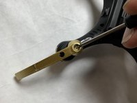
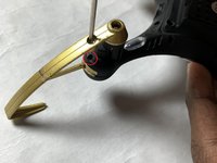
Remove the screws holding on the propeller guards using the Phillips #0 screwdriver (2 per propeller guard).
-
-
-
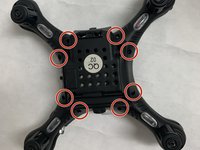
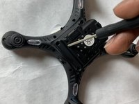
Using the Phillips #0 screwdriver to remove the eight screws securing the body of the drone.
-
-
-
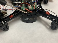
Depress the tab to open the battery housing.
-
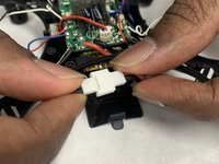
Disconnect the battery connectors
-
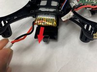
Remove the battery.
-
-
-
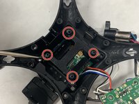
Using the Phillips #0 screwdriver, remove the four circuit board screws.
-
Remove circuit board.
-
-
-
-
Remove the four battery housing screws with the Phillips #0 screwdriver.
-
Remove the battery housing to reveal the camera circuit board underneath.
-
-
-
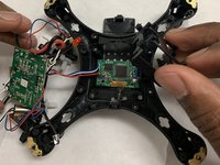
Remove camera circuit board from housing.
-
On the main circuit board, desolder the the connection points connecting to camera circuit board.
-
Four wires need to be desoldered. Colours include: Red, white, black and blue.
-

 Ask FixBot










To reassemble your device, follow these instructions in reverse order.

Team

IUPUI, Team S2-G2, Harley Fall 2019 Member of IUPUI, Team S2-G2, Harley Fall 2019
IUPUI-HARLEY-F19S2G2
3 Members
24 Guides authored
