Introduction
Use this guide to replace a worn-out display data cable.
What you need
-
-
Use a coin or a spudger to turn the battery locking screw 90 degrees clockwise.
-
Lift the battery out of the computer.
-
-
-
Remove the four Phillips screws from the memory door.
-
Slide the memory door away from the memory compartment.
-
-
-
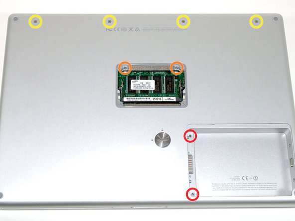
Remove the following 8 screws:
-
Two 3 mm Phillips in the battery compartment, on either side of the battery contacts.
-
Two 12 mm Phillips on either side of the memory compartment.
-
Four 16 mm Phillips along the hinge.
-
-
-
Rotate the computer 90 degrees clockwise, so that the power receptacle faces you.
-
Remove the three 3 mm Phillips screws.
-
-
-
Turn the computer 90 degrees clockwise so that the hinge faces you.
-
Remove the bottom 5 mm Phillips screw on either side of the hinge (two total).
-
-
-
Rotate the computer 90 degrees clockwise, so that the ports face you.
-
Remove the three 3 mm Phillips screws.
-
-
-
Turn the computer over and open the display.
-
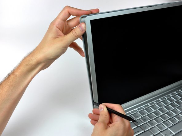
Remove the two 1.5 mm hex screws in either corner, next to the display (a T6 Torx driver will work, but repeated use will strip the screws).
-
-
-
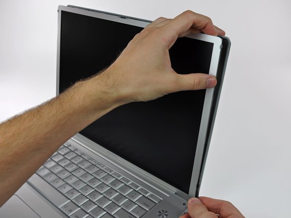
Grasp the back corners of the upper case and pull up. Do not pull the upper case off yet; you still need to disconnect the keyboard and trackpad cable.
-
Lift the back of the case up and work your fingers along the sides, freeing the case as you go. Once you have freed the sides, you may need to rock the case up and down to free the front of the upper case.
-
-
-
Remove the orange tape securing the trackpad ribbon to the logic board.
-
Disconnect the trackpad ribbon from the logic board.
-
Remove the upper case from the computer.
-
-
-
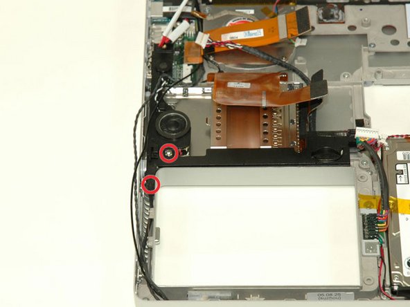
Remove the 9.5 mm silver Phillips screw from the top of the right ambient light sensor board.
-
Remove the small 3 mm black Phillips screw from the bottom of the board.
-
-
-
Remove the two black Phillips screws from the right speaker.
-
Lift the speaker away from the logic board and place it aside
-
-
-
Use your fingernail to flip up the black plastic flap locking the modem cable in place.
-
Slide the modem cable from its connector.
-
-
-
Remove the following 8 Phillips screws from the logic board:
-
Three 6.5 mm in the upper left corner.
-
Five 4.5 mm around the edges.
-
-
-
-
Grasp the logic board at the left edge with one hand and at the thinnest section with the other hand. Lift the left edge of the board up to approximately a 30 degree angle (if you don't have your protractor handy, just lift until the DVI port clears the right hinge).
-
Once the logic board clears the ports, slide it out to the left.
-
-
-
To properly reassemble your PowerBook, you'll have to clean off and replace the old thermal compound. Use our Applying Thermal Paste Guide to prepare the processor and heat sink surfaces.
-
-
-
Remove the two 3 mm black Phillips screws from the left ambient light sensor board.
-
Lift the left ambient light sensor board out of the computer, removing tape as necessary.
-
-
-
Remove the 4 mm hex nut from below the left speaker.
-
Remove the 3 mm black Phillips screw from bottom left corner of the speaker assembly, to the left of the battery compartment.
-
-
-
Remove the two 4.2 mm silver Phillips screws from the left corners of the PC card cage.
-
-
-
Remove the two 4.2 mm silver Phillips screws from either side of the large orange Airport ribbon.
-
-
-
Lift the Airport card out of the computer and slide a spudger between the card and the antenna connector to disconnect the cable from the card.
-
Deroute the antenna cable from the side of the card, removing tape as necessary.
-
You don't need to remove the Airport card entirely. We're just trying to free up the Airport antenna cable.
-
-
-
Using a spudger, pry up the Bluetooth board from the cavity in front of the battery compartment.
-
-
-
Close the display and turn the hinge side of the computer to face you.
-
Remove the remaining Phillips screw on either side of the hinge (two screws total).
-
-
-
Open the display and turn the computer so the screen faces you.
-
Remove the 10 mm T8 Torx screw closer to the display on either side of the hinge (two screws total).
-
-
-
Remove the longer 13 mm shouldered T8 Torx screw remaining on either hinge (two screws total).
-
-
-
Open the computer with the display facing you and rotate the display back as far as possible.
-
Remove the T6 Torx screw from the bottom left corner of the display assembly. The computer casing will not allow the screwdriver to be inserted directly into the screw, so be careful not to strip the screw.
-
-
-
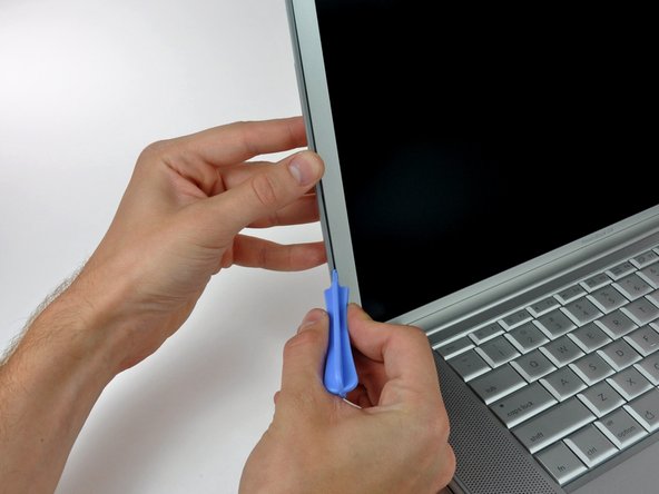
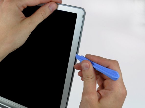
Insert a plastic opening tool between the left edge of the front display bezel and the plastic strip attached to the rear bezel, with the edge of the tool angled toward the LCD.
-
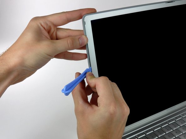
Rotate the tool away from the LCD to pop the rear bezel off the tabs on the front display bezel.
-
Work along the left edge of the display until the rear bezel is evenly separated from the front bezel.
-
-
-
Insert a plastic opening tool between the right edge of the front display bezel and the plastic strip attached to the rear bezel, with the edge of the tool angled toward the LCD.
-
Rotate the tool away from the LCD to pop the rear bezel off the tabs on the front display bezel.
-
Work along the right edge of the display until the rear bezel is evenly separated from the front bezel.
-
-
-
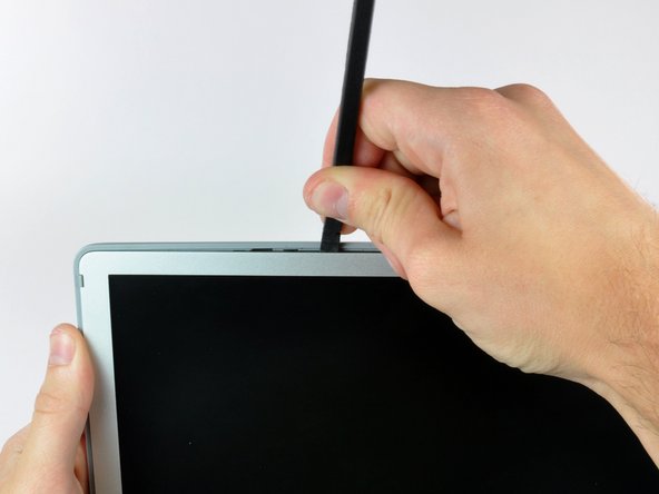
Insert a spudger just to the left of the hinge opening on the top edge of the display between the front display bezel and the plastic strip attached to the rear bezel.
-
Pry the rear bezel away from the front bezel along the top left half of the display.
-
-
-
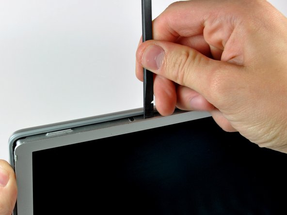
Insert a spudger just to the right of the hinge opening on the top edge of the display between the front display bezel and the plastic strip attached to the rear bezel.
-
Pry the rear bezel away from the front bezel along the top right half of the display.
-
-
-
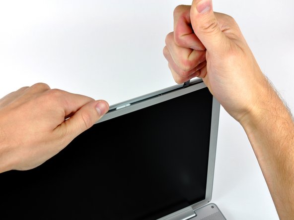
Now that the top edge is released, use a spudger to completely release the clips along the left edge of the display.
-
-
-
Close the display.
-
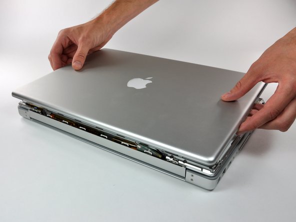
Rotate the top edge of the rear display bezel slightly away from the rest of the display, and then lift the lower edge of the rear bezel away from the clutch cover.
-
-
-
Carefully lift the antenna board out of the clutch assembly.
-
Peel the three self-adhesive flaps off the plastic cover on the underside of the antenna board.
-
Remove the protective plastic cover from the antenna board.
-
-
-
Use the flat end of a spudger to disconnect both antenna connectors from the antenna board.
-
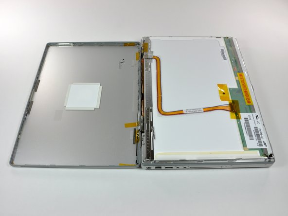
The rear bezel can now be completely removed from the LCD assembly.
-
-
-
Use a spudger to raise the end of the inverter out from the clutch cover.
-
Lift the inverter enough to access both cable connectors.
-
-
-
Disconnect both inverter cables by pulling their connectors away from the sockets on the inverter.
-
Remove the inverter from your display and set it aside.
-
-
-
Remove the five Phillips screws securing the LCD retaining bracket to the front display bezel.
-
Lift the LCD retaining bracket off the front display bezel.
-
-
-
Use your thumbs to push the clutch cover away from the clutch hinges.
-
While pressing with your thumbs, rotate the clutch cover toward yourself about its long edge to pop it off the clutch hinge.
-
It may be necessary to wiggle the clutch cover while pressing it away from the clutch hinges to release the retaining clips.
-
-
-
Repeat this process for the other side of the clutch cover. Once the clutch cover is completely free from the clutch hinges, lift it off the front display bezel.
-
-
-
Pull the display data cable connector away from its socket to disconnect it from the LCD.
-