Introduction
In contrast to the X and Y axes, the built-in Z axis sensor is a potentiometer and not a Hall sensor. After a few weeks, the Z-axis of my joystick began to deflect to the left in an uncontrolled manner. According to entries in various forums, this happens more frequently with this type, as well as with the very similar T.16000M.
The replacement of potentiometers with (practically) wear-free Hall sensors of the Honeywell SS495A type has already been described for other joysticks (see Reddit). The TCA Airbus Stick only supplies the potentiometer with 3.3V and thus outside the manufacturer's specification of the SS495A, which specifies a minimum voltage of 4.5V. Nevertheless, this cheap and easily obtainable sensor also works perfectly in this joystick.
What you need
-
-
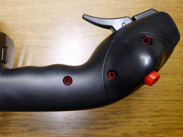
In order to disassemble the joystick, two medium-length PH2 screws must be unscrewed at the base and one more on the side of the handle. In addition, the two long screws that anchor the interchangeable knobs 3 and 4 must be unscrewed. Below the interchangeable knobs, two short screws still need to be removed.
-
-
-
Cable assignment: Brown = 0V; Orange = 3.3V; Red = signal
-
The Z-axis potentiometer is stuck with the shaft in the non-rotatable, inner carrier of the joystick. The shaft is not glued and the potentiometer can be easily pulled out. The cables are protected by a bead of adhesive which must be carefully removed. Then the three cables can be unsoldered.
-
-
-
-
The Honeywell SS495A Hall sensor, which can be bought from Reichelt or Conrad, is soldered on as follows: the orange cable to pin 1, brown to pin 2 and red to pin 3.
-
The sensor can now be glued flat (as can be seen in the picture) to the non-rotatable stem. Its top edge must be about 1.5 to 2.0mm from the edge of the stem. The closer the sensor is to the edge, the more sensitive it will be to the movement of the magnet. The sensor must be mounted as centrally and straight as possible.
-
I recommend using hot glue as position is absolutely critical to function and it probably won't work out satisfactorily on the first try. Unfortunately, this requires a bit of patience and finesse. Hot glue can be easily removed from the plastic of the joystick.
-
I used a 4 mm long bar magnet with a diameter of 3 mm (manufacturer MEDER item no. 4003004025). This is available from Reichelt under the name "MAGNET 3.4". I used hot glue to glue the magnet into the inside of the (slightly wider) right half shell so that it sits in the middle just above the Hall sensor.
-
Attention: The orientation of the magnet determines the deflection of the Hall sensor. If the mounting direction is wrong, the Z-axis will be inverted. Please check the function.
-
In the middle position, the output of the Hall sensor should deliver VS/2 = 1.66V. With a left turn, the output voltage must drop. Turning it to the right (clockwise) increases it accordingly.
-
-
-
If you hold the right half-shell to the handle, the function of the joystick can be checked with an appropriate test program (like the one integrated in Windows). The joystick can also be turned carefully in this state, as long as you hold the half-shell pressed tightly against the handle without play.
-
-
-
With good positioning of the components, the raw value is 0 in the middle position. When turning the joystick, the minimum and maximum value should be reached.
-


Finally, the joystick can be reassembled. To do this, the plastic part for fixing the Z-axis must be inserted between the handle and the half-shells and the circuit board with the upper buttons must be brought into position. The half-shells can then be screwed on again. Lastly, the interchangeable knobs are mounted using the longest screws. Finished!
Finally, the joystick can be reassembled. To do this, the plastic part for fixing the Z-axis must be inserted between the handle and the half-shells and the circuit board with the upper buttons must be brought into position. The half-shells can then be screwed on again. Lastly, the interchangeable knobs are mounted using the longest screws. Finished!
Cancel: I did not complete this guide.
One other person completed this guide.
Special thanks to these translators:
100%

oldturkey03 is helping us fix the world! Want to contribute?
Start translating ›

2 Comments
Spitze ,danke.
Ich habe es heute versucht und musste feststellen, dass der genannte Hallsensor von Conrad sehr viel kleiner ist, als hier auf den Fotos. Echte Fummelei und der Ausschlag links/recht -nach der Heissklebeprozedur des Sensors- reichte nicht aus für max. Steuerungswege des Seitenruders. Ich habe alles wieder zurück gebaut, so konnte nicht bleiben. Wenn das Poti wieder wackelig wird, versuche ich es ggf. noch einmal.