Introduction
Removing the shutter from a Pentax MX should only be done to fix major issues such as, torn curtains, broken curtain strings, or very dirty shutter components. It is not part of normal preventative maintenance. It also requires specialized testing equipment to recalibrate the curtain speeds and the exposure time after reassembly.
What you need
-
-
Remove the lever cap. The cap is reverse threaded.
-
Lift off the advance lever.
-
Remove the collar beneath the lever.
 Ask FixBot
-
-
-
Set the ISO to 100 and the shutter speed to 1000.
-
Remove one pin head screw.
-
Lift off shutter speed dial.
-
Remove the collar beneath the dial.
-
Installation Notes: Make sure that the tab on the shutter speed resistor mates properly with this slot on the shutter speed dial.
-
-
-
Place a tool in the fork of the rewind shaft. Turn the rewind knob counterclockwise to loosen it.
-
Remove the lock ring underneath the rewind knob.
-
Remove the cover plate.
-
-
-
Remove two M1.7 x 3.2 mm screws.
-
Remove two M1.7 x 2 mm countersunk screws.
-
Lift off top cover.
-
The release cable pin in the shutter button is loose and may fall out.
-
-
-
Apply isopropyl alcohol to soften the leatherette adhesive.
-
Turn the self-timer lever to the charged position.
-
Peel the leatherette off the camera body, carefully working it over the self-timer lever.
-
Remove one loose cover panel.
-
Repeat for the opposite panel.
-
-
-
Unsolder two yellow wires for the aperture resistor.
-
-
-
Remove four M1.9 x 3.9 mm screws.
-
Lift off front board.
-
Look for shim washers at the screw locations and note their positions.
-
-
-
Remove three M1.7 x 2.0 mm countersunk screws.
-
Lift off bottom cover.
-
Remove loose plastic housing for motor drive contacts.
-
-
-
Remove four M1.9 x 3.8 mm screws.
-
Lift off light baffle.
-
Use isopropyl alcohol to soften adhesive and detach wires from the backside of the baffle.
-
-
-
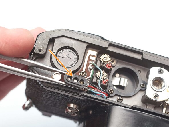
Unsolder two brown wires for the shutter speed resistor.
-
-
-
Unsolder one gray for the x-sync.
-
Unsolder one white wire for the FP sync.
-
-
-
Unsolder one green wire for the motor drive connection.
-
Unsolder one blue wire for the LED switch.
-
Unsolder one red wire and one black wire.
-
-
-
Open up wire routing guides and remove all wires from them.
-
Pull the black and red wires out of the hole in the bottom of the chassis.
-
Make sure the gray wire is free and can pull away with the mirror box.
-
-
-
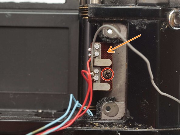
Remove one M1.4 x 2.8 mm screw and washer.
-
Remove one M1.7 x 2.8 mm screw.
-
Pull the LED PCB out of the side of the mirror box.
-
-
-
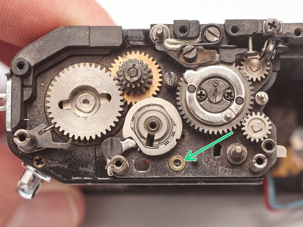
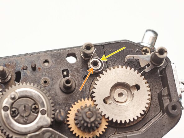
Loosen the slotted post but do not remove.
-
Slide the idler gear back so that it no longer engages with the speed indicator disc.
-
-
-
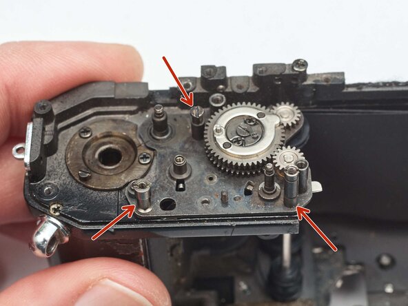
Remove two M1.7 x 4.6 mm screws.
-
Remove two slotted posts.
-
Lift the mirror box up and tilt the top forward to remove it.
-
-
-
Temporarily install the wind lever and the shutter speed dial.
-
Wind the camera.
-
Press the shutter release button.
-
Release the opening curtain latch. This is usually done by the mirror box but has to be done manually in this case.
-
-
-
Temporarily replace the wind lever and move it into the stowed position.
-
Remove one M1.7 x 2.4 mm countersunk screw.
-
Remove one M1.7 x 3.8 mm screw.
-
Remove one M1.4 slotted nut.
-
Lift off frame counter mechanism.
-
-
-
-
Align the post on the ratcheting gear with the slot in the top wind gear.
-
The frame counter gears will also need to mesh when installed.
-
Check the placement of this spring. It often comes loose.
-
-
-
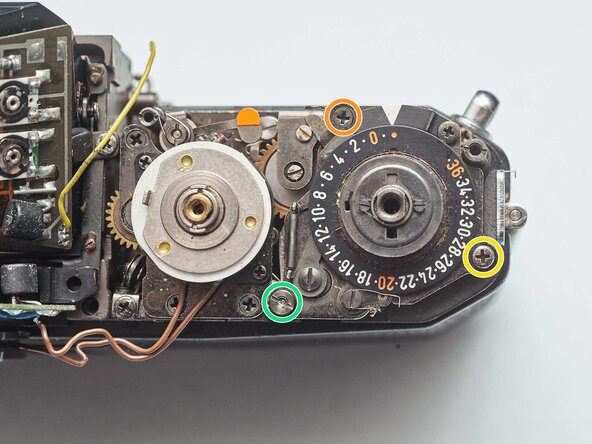
Remove two screws.
-
Lift off shutter speed resistor.
-
-
-
Remove two screws.
-
Lift off support plate. It is still connected to the shutter speed dial by a thin cable.
-
Remove two shim washers.
-
Remove the door latch spring arm.
-
Installation Notes: Route the cable through the pulleys as shown before installing the support plate.
-
-
-
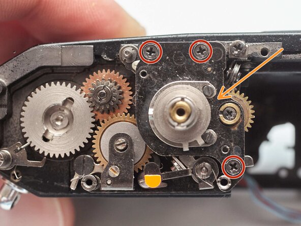
Remove three screws.
-
Remove speed selector plate
-
Lift off high speed cam.
-
Remove spacer washer.
-
-
-
Clean the high speed cam and the seat that it operates in. Apply shutter oil to the shaft and hole.
-
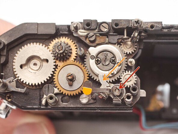
Set the speed selector to the '1000' position.
-
The cam for the slow speed governor should be in this position to sync properly with the speed selector.
-
Ensure that the shaft to the slow speed governor couples properly.
-
-
-
Mark the vertical position of the shutter release arm on the release shaft.
-
Remove two M1.4 x 2.4 mm screws.
-
Remove shutter release arm.
-
-
-
Remove one M1.4 x 2.4 mm screw.
-
Remove the shutter release plate.
-
Slide the shutter release shaft out from the bottom of the camera.
-
Keep track of the coil spring as it slides off.
-
-
-
Remove one M1.4 slotted nut.
-
Push the latch out from between the wind gears and slide it off the shaft.
-
Installation Notes: Note the position of the bias springs during installation.
-
-
-
Remove one slotted post.
-
Remove plate.
-
Remove upper transport gear latch.
-
Remove upper transport gear.
-
-
-
Shutter curtains should be in the wound state...
-
And the lower transport gear latch engaged.
-
Place the upper transport gear such that the right side of the slot is as close to the transport latch as possible without touching or rubbing.
-
-
-
Unhook bias spring.
-
Remove one M1.4 x 2.8 mm shoulder screw.
-
Remove lower transport gear latch and bias spring.
-
Remove washer.
-
-
-
Remove one M1.4 x 2.4 mm screw.
-
Remove washer.
-
Remove bias spring.
-
-
-
Lubricate the pinion shafts. On the wind side, the pinions turn in their end pivots. The oil should be between the shafts and the end plates.
-
Lubricate the rollers. On the rewind side, the rollers turn on the fixed shafts. The oil should be between the rollers and the shafts.
-
-
-
Remove two screws.
-
Pull the battery compartment towards the bottom of the camera.
-
Note the routing of the red wire.
-
-
-
Unsolder two blue wires for the shutter button switch.
-
Unsolder one green wire.
-
Pull the wires out through the hole in the chassis so they are free.
-
-
-
Remove one screw.
-
Lift away the flash sync PCB. It is still connected by the red wires.
-
-
-
Use isopropyl alcohol to soften the adhesive holding the wires.
-
Remove two screws.
-
Remove the X sync contact.
-
-
-
Use isopropyl alcohol to soften the adhesive holding the wires.
-
Remove two screws.
-
Lift off the main meter switch and gently pull the blue wires through the hole in the chassis.
-
-
-
Remove one circlip.
-
Remove the slow speed coupling rod through the bottom of the chassis.
-
-
-
Remove one screw.
-
Lift off closing curtain delay gear.
-
-
-
Clean the gear shaft and lubricate with shutter oil.
-
Charge the shutter. Manually push the opening curtain latch forward once the shutter is wound to hold it in position.
-
Temporarily install the slow speed governor.
-
Install the closing curtain delay gear such that the gap between the two governor plates is parallel.
-
Remove the slow speed governor.
-
Check that the stud on the bottom of the gear properly actuates the mirror release lever when the shutter is fired.
-
-
-
Remove one slotted screw.
-
Lift off closing curtain pinion gear.
-
-
-
Remove two screws.
-
Remove shutter curtain baffle.
-
-
-
Remove stopper spring.
-
Remove one slotted post.
-
Remove washer.
-
Measure the distance that the stopper adjustment extends from the rear wall and record the value for reference during reassembly.
-
Remove the slotted stopper adjustment screw.
-
-
-
Remove one screw.
-
Remove indicator cable pulley.
-
-
-
Remove one slotted screw.
-
Remove oil wick and retainer plate.
-
Remove retaining post using a spanner wrench.
-
Remove curtain travel stop.
-
-
-
Use isopropyl alcohol to soften the screw locker on two set screws.
-
Loosen the set screws.
-
Loosen the tension adjustment until the rollers no longer pull the curtains.
-
Hold the roller shaft gear in place and unscrew the adjustment worm gear to remove it.
-
-
-
Remove two screws.
-
Remove indicator cable adjustment plate.
-
Remove two shim washers.
-
Remove one curtain string pulley.
-
Installation Notes: The ends of the roller shafts sit in two holes in the indicator cable adjustment plate. Make sure those are properly seated before screwing down the plate.
-
-
-
Use a slotted screw driver to hold the roller shaft in place.
-
Use a second slotted screwdriver to remove the roller shaft gears. They are reverse threaded.
-
Remove the curtain rollers.
-
-
-
Remove three slotted posts.
-
Lift the wind gear plate upward and out of the chassis.
-
-
-
Note the position of the curtains. The closing curtain (left) should sit in front of the opening curtain (right).
-
Note the routing of the curtain strings. The opening curtain strings should run behind the plastic rollers.
-
The upper string is kept in place by a metal tab that covers the roller.
-
Install the wind gear plate first, making sure that the curtain strings are properly routed as it is put in place.
-
Install the roller shafts second.
-


To reassemble your device, follow these instructions in reverse order.