Introduction
Removing the mirror box is often necessary to troubleshoot issues and access mechanisms for cleaning. The mechanisms on the side and bottom of the mirror box are common sources of a jammed camera.
What you need
-
-
-
Remove the lever cap. The cap is reverse threaded.
-
Lift off the advance lever.
-
Remove the collar beneath the lever.
 Ask FixBot
-
-
-
Set the ISO to 100 and the shutter speed to 1000.
-
Remove one pin head screw.
-
Lift off shutter speed dial.
-
Remove the collar beneath the dial.
-
Installation Notes: Make sure that the tab on the shutter speed resistor mates properly with this slot on the shutter speed dial.
-
-
-
Place a tool in the fork of the rewind shaft. Turn the rewind knob counterclockwise to loosen it.
-
Remove the lock ring underneath the rewind knob.
-
Remove the cover plate.
-
-
-
Remove two M1.7 x 3.2 mm screws.
-
Remove two M1.7 x 2 mm countersunk screws.
-
Lift off top cover.
-
The release cable pin in the shutter button is loose and may fall out.
-
-
-
-
-
Apply isopropyl alcohol to soften the leatherette adhesive.
-
Turn the self-timer lever to the charged position.
-
Peel the leatherette off the camera body, carefully working it over the self-timer lever.
-
Remove one loose cover panel.
-
Repeat for the opposite panel.
-
-
-
Unsolder two yellow wires for the aperture resistor.
-
-
-
-
Remove four M1.9 x 3.9 mm screws.
-
Lift off front board.
-
Look for shim washers at the screw locations and note their positions.
-
-
-
-
-
Remove three M1.7 x 2.0 mm countersunk screws.
-
Lift off bottom cover.
-
Remove loose plastic housing for motor drive contacts.
-
-
-
-
-
Remove four M1.9 x 3.8 mm screws.
-
Lift off light baffle.
-
Use isopropyl alcohol to soften adhesive and detach wires from the backside of the baffle.
-
-
-
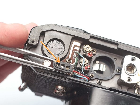
Unsolder two brown wires for the shutter speed resistor.
-
-
-
Unsolder one gray for the x-sync.
-
Unsolder one white wire for the FP sync.
-
-
-
Unsolder one green wire for the motor drive connection.
-
Unsolder one blue wire for the LED switch.
-
Unsolder one red wire and one black wire.
-
-
-
Open up wire routing guides and remove all wires from them.
-
Pull the black and red wires out of the hole in the bottom of the chassis.
-
Make sure the gray wire is free and can pull away with the mirror box.
-
-
-
Remove one M1.4 x 2.8 mm screw and washer.
-
Remove one M1.7 x 2.8 mm screw.
-
Pull the LED PCB out of the side of the mirror box.
-
-
-
Loosen the slotted post but do not remove.
-
Slide the idler gear back so that it no longer engages with the speed indicator disc.
-
-
-
Remove two M1.7 x 4.6 mm screws.
-
Remove two slotted posts.
-
Lift the mirror box up and tilt the top forward to remove it.
-
-
-
Temporarily install the wind lever and the shutter speed dial.
-
Wind the camera.
-
Press the shutter release button.
-
Release the opening curtain latch. This is usually done by the mirror box but has to be done manually in this case.
-
-


To reassemble your device, follow these instructions in reverse order.