
Optical Laser Lens Power Adjustment

What you need

  1. Optical Laser Lens Power Adjustment, Top Case: step 1, image 1 of 3 Optical Laser Lens Power Adjustment, Top Case: step 1, image 2 of 3 Optical Laser Lens Power Adjustment, Top Case: step 1, image 3 of 3
    • Turn over the Gamecube so that the bottom side is facing up.

    • Use the 4.5 mm Gamebit screwdriver to remove all four screws.

  2. Optical Laser Lens Power Adjustment: step 2, image 1 of 3 Optical Laser Lens Power Adjustment: step 2, image 2 of 3 Optical Laser Lens Power Adjustment: step 2, image 3 of 3
    • With the bottom side of the GameCube facing upward and the screws removed, carefully pull the outer shell of the unit away from the top half.

    • Move the GameCube so that the inside is facing upwards.

  3. Optical Laser Lens Power Adjustment, Removing the back panel: step 3, image 1 of 1
    • Gently press down on the clips located on either side of the back panel.

    • Carefully remove the back panel from the GameCube.

  4. Optical Laser Lens Power Adjustment: step 4, image 1 of 1
    • Unclip the controller ports at the front of the unit.

    • A ribbon cable (outlined in orange) is still attached to the unit. Do not disconnect this cable.

    • Controller ports are where the controllers plug into the game console, and are a half circular shape.

  5. Optical Laser Lens Power Adjustment, Separate the casing: step 5, image 1 of 2 Optical Laser Lens Power Adjustment, Separate the casing: step 5, image 2 of 2
    • Use a Phillips #2 screwdriver to remove the two screws on the back of the control port.

    • Carefully separate the gray outer casing of the control port and the circuit board.

  6. Optical Laser Lens Power Adjustment, Remove Nintendo GameCube Optical Drive Assembly: step 6, image 1 of 2 Optical Laser Lens Power Adjustment, Remove Nintendo GameCube Optical Drive Assembly: step 6, image 2 of 2
    • The left side of the unit contains the cooling fan and its housing.

    • Carefully remove the two screws attaching the cooling fan housing to the unit.

    • Do not detach the red and black cooling fan wire from the main unit. Boxed in orange.

  7. Optical Laser Lens Power Adjustment: step 7, image 1 of 2 Optical Laser Lens Power Adjustment: step 7, image 2 of 2
    • Remove the four Phillips #1 screws retaining the ground springs.

    • Carefully remove the ground springs from the main unit.

  8. Optical Laser Lens Power Adjustment: step 8, image 1 of 2 Optical Laser Lens Power Adjustment: step 8, image 2 of 2
    • The optical drive is secured to a metal plate.

    • Using a Phillips #2 screwdriver, unscrew the twelve screws that are around the outer edge of the optical drive.

  9. Optical Laser Lens Power Adjustment, Remove the assembly: step 9, image 1 of 3 Optical Laser Lens Power Adjustment, Remove the assembly: step 9, image 2 of 3 Optical Laser Lens Power Adjustment, Remove the assembly: step 9, image 3 of 3
    • Carefully separate the optical drive assembly from the rest of the GameCube unit.

    • The optical drive assembly is secured to the motherboard underneath by a slot; some force may be required to carefully free the assembly.

    • The metal plate and the actual optical drive will remain attached.

  10. Optical Laser Lens Power Adjustment, Optical Drive Assembly: step 10, image 1 of 3 Optical Laser Lens Power Adjustment, Optical Drive Assembly: step 10, image 2 of 3 Optical Laser Lens Power Adjustment, Optical Drive Assembly: step 10, image 3 of 3
    • At this point, your optical drive assembly should be separated from your GameCube.

    • Flip the optical drive assembly upside down.

    • Remove the six screws with a Phillips #1 screwdriver.

    • Gently lift and remove the metal plate.

    • Be careful not to disturb the brown ribbon cable.

  11. Optical Laser Lens Power Adjustment: step 11, image 1 of 3 Optical Laser Lens Power Adjustment: step 11, image 2 of 3 Optical Laser Lens Power Adjustment: step 11, image 3 of 3
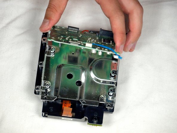
    • Remove the blue wire by gently pulling.

    • Don't pull on either the wire itself or the connector attached to the board.

    • Disconnect the brown cable. This is done by gently pulling the black tab away from the white plastic. This will loosen the tension on the brown cable, allowing it to slide away from the tab gently.

    • Remove the four Phillips #1 screws connecting the circuit board to the optical drive assembly.

    • The fourth screw is located behind the screwdriver in the third picture.

  12. Optical Laser Lens Power Adjustment: step 12, image 1 of 3 Optical Laser Lens Power Adjustment: step 12, image 2 of 3 Optical Laser Lens Power Adjustment: step 12, image 3 of 3
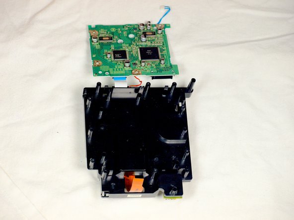
    • Release the small clip holding the board down.

    • Gently remove the circuit board (the large green square) as shown in the three pictures.

    • DO NOT SEPARATE the red wire or the white ribbon cable connecting the circuit board to the metal plate.

    • Red Wire

    • White ribbon Cable

  13. Optical Laser Lens Power Adjustment: step 13, image 1 of 3 Optical Laser Lens Power Adjustment: step 13, image 2 of 3 Optical Laser Lens Power Adjustment: step 13, image 3 of 3
    • Use a flathead screwdriver to carefully release the four plastic clips holding the drive assembly together.

    • Carefully use a screwdriver as leverage to unscrew and release the last clip.

  14. Optical Laser Lens Power Adjustment: step 14, image 1 of 3 Optical Laser Lens Power Adjustment: step 14, image 2 of 3 Optical Laser Lens Power Adjustment: step 14, image 3 of 3
    • Gently lift the metal plate off the drive assembly.

    • Be careful not to sever the red wire or the white ribbon cable still attached to the two halves of the drive assembly.

    • Then, flip the two halves of the drive assembly upside down.

  15. Optical Laser Lens Power Adjustment: step 15, image 1 of 3 Optical Laser Lens Power Adjustment: step 15, image 2 of 3 Optical Laser Lens Power Adjustment: step 15, image 3 of 3
    • Use a flathead screwdriver to release the two clips located on the back half of the drive assembly.

    • The final clip doesn't need to be released; the top half of the drive assembly will slide away from the lower half.

    • Finish removing the top half of the drive assembly from the base.

    • Be careful not to detach the red wire or the white ribbon cable still attached.

  16. Optical Laser Lens Power Adjustment: step 16, image 1 of 2 Optical Laser Lens Power Adjustment: step 16, image 2 of 2
    • Once the top half of the drive assembly is detached, turn it upside down.

    • Using a Phillips #1 screwdriver, carefully remove the three final screws near the lens assembly bars.

    • Extract the final three screws and remove the lens assembly.

  17. Optical Laser Lens Power Adjustment, Optical Laser Lens Power Adjustment: step 17, image 1 of 2 Optical Laser Lens Power Adjustment, Optical Laser Lens Power Adjustment: step 17, image 2 of 2
    • Rotate the assembly so that the green circuit board is facing you as shown in the first picture.

    • Flip board over so it is oriented as shown in the second picture.

    • Using a Phillips #1 Screwdriver, turn the small knob very slightly counter-clockwise—a few degrees to, at most, one-quarter turn.

    • You can find instructions for testing to make sure your repair worked at this link.

agronbac

Member since: 10/28/09

739 Reputation

1 Guide authored

Team

Cal Poly, Team 6-2, Maness Fall 2009 Member of Cal Poly, Team 6-2, Maness Fall 2009

CPSU-MANESS-F09S6G2

4 Members

45 Guides authored

View Statistics:

Past 24 Hours: 60

Past 7 Days: 564

Past 30 Days: 2,127

All Time: 114,058