
Installing Nintendo DSi XL Lower Display Assembly

Prerequisite Only
This guide is only intended to be used as a prerequisite for other guides. It's incomplete by itself.

What you need

  1. Installing Nintendo DSi XL Lower Display Assembly, Battery: step 1, image 1 of 2 Installing Nintendo DSi XL Lower Display Assembly, Battery: step 1, image 2 of 2
    • Remove the two Phillips screws securing the battery cover to the back of the handheld console.

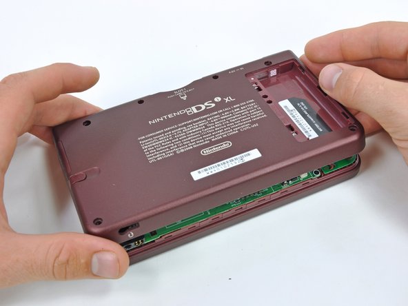
    • Lift the battery cover off the back of the DSi XL.

  2. Installing Nintendo DSi XL Lower Display Assembly: step 2, image 1 of 1
    • Lift the battery from the DSi XL.

  3. Installing Nintendo DSi XL Lower Display Assembly, Lower Case: step 3, image 1 of 3 Installing Nintendo DSi XL Lower Display Assembly, Lower Case: step 3, image 2 of 3 Installing Nintendo DSi XL Lower Display Assembly, Lower Case: step 3, image 3 of 3
    • Remove the four rubber screw covers on the lower case by prying them up with a push pin.

  4. Installing Nintendo DSi XL Lower Display Assembly: step 4, image 1 of 1
    • Remove the following seven Phillips screws that secure the lower case to the rest of the DSi XL:

    • Four silver 5.3 mm screws

    • Two black 5.3 mm screws

    • One black 2.5 mm screw

  5. Installing Nintendo DSi XL Lower Display Assembly: step 5, image 1 of 3 Installing Nintendo DSi XL Lower Display Assembly: step 5, image 2 of 3 Installing Nintendo DSi XL Lower Display Assembly: step 5, image 3 of 3
    • Turn the DSi XL over, and open the display.

    • Insert a spudger between the upper and lower case at the bottom left corner of the DSi.

    • Slide the spudger along the bottom edge of the upper case to release the latches securing the upper case to the lower case.

  6. Installing Nintendo DSi XL Lower Display Assembly: step 6, image 1 of 2 Installing Nintendo DSi XL Lower Display Assembly: step 6, image 2 of 2
    • Close the display and turn the DSi XL over.

    • Lift the lower case from the front edge.

    • Rotate the lower case away from the DSi.

    • The lower case cannot be completely removed yet, since it is still connected to the motherboard.

  7. Installing Nintendo DSi XL Lower Display Assembly: step 7, image 1 of 2 Installing Nintendo DSi XL Lower Display Assembly: step 7, image 2 of 2
    • Using a spudger, pry the SD card/right shoulder button connector off its socket.

    • Pry the volume button/left shoulder button connector off its socket on the motherboard with a spudger.

  8. Installing Nintendo DSi XL Lower Display Assembly, Wi-Fi Board: step 8, image 1 of 2 Installing Nintendo DSi XL Lower Display Assembly, Wi-Fi Board: step 8, image 2 of 2
    • Lift the Wi-Fi board up off its socket on the motherboard.

    • Do not attempt to completely remove the Wi-Fi board yet. It is attached to the motherboard by an antenna cable.

  9. Installing Nintendo DSi XL Lower Display Assembly: step 9, image 1 of 1
    • Use a spudger to pry the Wi-Fi cable off its socket on the underside of the Wi-Fi board.

  10. Installing Nintendo DSi XL Lower Display Assembly, Motherboard: step 10, image 1 of 1
    • Use a spudger to pry the microphone cable off the motherboard.

    • Pry from underneath the cable.

  11. Installing Nintendo DSi XL Lower Display Assembly: step 11, image 1 of 2 Installing Nintendo DSi XL Lower Display Assembly: step 11, image 2 of 2
    • Using the flat end of a spudger, flip up the retaining flap on the camera ribbon ZIF connector.

    • Use the pointed end of a spudger to pull the camera ribbon from the ZIF connector.

  12. Installing Nintendo DSi XL Lower Display Assembly: step 12, image 1 of 2 Installing Nintendo DSi XL Lower Display Assembly: step 12, image 2 of 2
    • Using the flat end of a spudger, flip up the retaining flap on the touchscreen cable ZIF connector.

    • With the pointed end of the spudger, pull the touchscreen cable from its connector on the motherboard.

  13. Installing Nintendo DSi XL Lower Display Assembly: step 13, image 1 of 2 Installing Nintendo DSi XL Lower Display Assembly: step 13, image 2 of 2
    • Using the flat end of a spudger, flip up the retaining flap on the backlight cable ZIF connector.

    • With the pointed end of the spudger, pull the backlight cable from its connector on the motherboard.

  14. Installing Nintendo DSi XL Lower Display Assembly: step 14, image 1 of 2 Installing Nintendo DSi XL Lower Display Assembly: step 14, image 2 of 2
    • Using the flat end of a spudger, flip up the retaining flap on the lower display data cable ZIF connector.

    • With the pointed end of the spudger, pull the lower display data cable from its connector on the motherboard.

  15. Installing Nintendo DSi XL Lower Display Assembly: step 15, image 1 of 2 Installing Nintendo DSi XL Lower Display Assembly: step 15, image 2 of 2
    • Using the flat end of a spudger, flip up the retaining flap on the ZIF connector for the D-Pad/power button cable.

    • With the pointed end of the spudger, pull the D-Pad/power button cable from its connector on the motherboard.

  16. Installing Nintendo DSi XL Lower Display Assembly: step 16, image 1 of 1
    • Using the flat end of the spudger, pry the battery cable up off its socket on the motherboard.

  17. Installing Nintendo DSi XL Lower Display Assembly: step 17, image 1 of 1
    • Remove the screws securing the motherboard to the upper case:

    • A single 2.5 mm silver Phillips screw

    • Four 3.7 mm black Phillips screws

  18. Installing Nintendo DSi XL Lower Display Assembly: step 18, image 1 of 1
    • Deroute the microphone and antenna cables through the slot in the motherboard.

  19. Installing Nintendo DSi XL Lower Display Assembly: step 19, image 1 of 2 Installing Nintendo DSi XL Lower Display Assembly: step 19, image 2 of 2
    • Rotate the motherboard off the lower case.

    • The motherboard cannot be completely removed yet. It is still attached by the upper LCD's display data ribbon cable.

  20. Installing Nintendo DSi XL Lower Display Assembly: step 20, image 1 of 2 Installing Nintendo DSi XL Lower Display Assembly: step 20, image 2 of 2
    • Using the flat end of a spudger, flip up the retaining flap on the upper display data cable ZIF connector.

    • With the pointed end of the spudger, pull the upper display data cable from its connector on the underside of the motherboard.

    • The motherboard is now free from the upper case.

  21. Installing Nintendo DSi XL Lower Display Assembly, Lower Display Assembly: step 21, image 1 of 2 Installing Nintendo DSi XL Lower Display Assembly, Lower Display Assembly: step 21, image 2 of 2
    • With the console still upside-down, open the DSi XL slightly.

    • Push the lower display away from the upper case.

    • Remove the lower display from the DSi XL.

Brett Hartt

Member since: 04/12/10

127,926 Reputation

143 Guides authored

Team

iFixit Member of iFixit

Staff

135 Members

17,198 Guides authored

View Statistics:

Past 24 Hours: 2

Past 7 Days: 8

Past 30 Days: 8

All Time: 772