This translation was generated by a machine and has not been reviewed by a person yet. Speak this language? Review it.
Introduction
This guide shows how to replace the part of the power button that is soldered to the PCB. If you don't have any soldering skills yet, here is a tutorial .
What you need
-
-
-
Unscrew the Phillips screw securing the battery cover to the lower case.
-
Pry the battery cover upward with a spudger or fingernail, and lift out of the lower case.
 Ask FixBot
-
-
-
Wedge the edge of a spudger in between the side of the battery and the lower case housing and pry upward to dislodge the battery.
-
Remove the battery from the DS Lite.
-
-
-
-
-
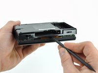
Use the tip of a spudger to pry both rubber feet off the DS Lite.
-
-
-
Remove the following screws securing the lower case to the body of the DS Lite:
-
Two 4.3 mm gold Phillips screws
-
One 3.9 mm black Tri-point screw
-
One 3.3 mm silver Phillips screw
-
Three 5.5 mm silver Tri-point screws
-
-
-
Insert the edge of a spudger in between the lower and upper case near the top right corner of the DS Lite.
-
Carefully run the spudger along the right edge of the DS Lite, creating an opening in the process.
-
Continue running the spudger along the backside of the DS Lite until the majority of the lower case has been separated from the upper case.
-
-
-
-
-
-
Use the flat edge of a spudger to pry the Wi-Fi antenna connector straight up from its socket on the Wi-Fi board.
-
-
-
Use the flat edge of a spudger to pry the Wi-Fi board connector straight up from its socket on the motherboard.
-
-
-
Use the flat edge of a spudger to separate the right edge of the Wi-Fi board from the motherboard.
-
Remove the Wi-Fi board from the DS Lite.
-
-
-
-
-
Use the flat edge of a spudger to pry the microphone connector straight up from its socket on the motherboard.
-
-
-
Position the antenna cable with its connector facing up and away from the motherboard using a spudger to hold it down lightly in the gap between chips on the motherboard.
-
Slowly and carefully pull the antenna cable until the cable connector is under the DS Lite game cartridge reader.
-
Continue pulling the cable until the cable connector comes out from under the game cartridge reader on the right side.
-
-
-
Use your fingernail or the edge of a spudger to carefully flip up the touchscreen ribbon cable retaining flap.
-
Use the tip of a spudger to pull the touchscreen ribbon cable straight out of its socket.
-
-
-
Remove the two 3.4 mm Phillips screws securing the motherboard to the upper case.
-
-
-
Open the display enough to use your finger to push the front edge of the motherboard up and away from the upper case.
-
-
-
Use your fingernail or the flat edge of a spudger to carefully flip up the upper LCD ribbon cable retaining flap.
-
Pull the motherboard away from the DS Lite to separate the upper LCD ribbon cable from its socket on the motherboard.
-
Remove the motherboard from the DS Lite.
-
Now you may open the retaining flap for the lower LCD screen in the same way and separate the lower LCD screen from the motherboard.
-
-
-
-
-
-
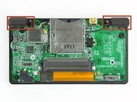
The power button is located in the upper right corner of the logic board, directly behind the right bumper.
-
-
-
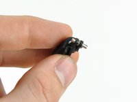
The power button is attached to the PCB with six solder points. There are also two plastic pegs located underneath the power button.
-
To prepare, you should first add some fresh solder to each of the six solder joints.
-
To desolder, hold the desoldering wick between the solder joint and the soldering iron, and press the iron onto the wick for a few seconds until it turns silver.
-
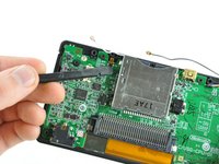
You can use tweezers to check if the individual pins are properly desoldered. To do this, press the tweezers against the side of the pin and see if it moves.
-
-








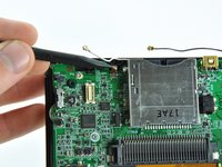


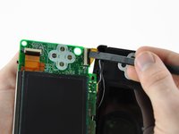
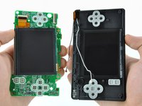


Follow the steps in reverse order to reassemble your device.
Cancel: I did not complete this guide.
One other person completed this guide.