Introduction
This guide is to display how to replace various parts in a cash register terminal and some minor maintenance.
What you need
-
-
You will need the security key that came with the register to unlock the front panel.
-
There are two screws in the back to release the cover.
-
-
-
-
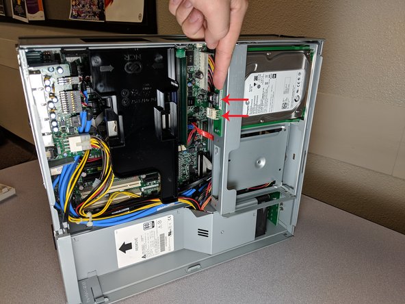
Disconnect all cables that are coming from the power supply.
-
Be sure to check the normal 24 and 4 pin power supply cables. But also look around for any supporting components that require power.
-
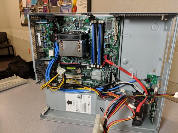
Remove the power supply by pulling it towards yourself . (As is you are looking down at the device).
-


To reassemble your device, follow these instructions in reverse order.
To reassemble your device, follow these instructions in reverse order.
Cancel: I did not complete this guide.
One other person completed this guide.
Team

University of Advancing Technology, Team S1-G5, Beam Spring 2019 Member of University of Advancing Technology, Team S1-G5, Beam Spring 2019
UAT-BEAM-S19S1G5
3 Members
1 Guide authored
One Comment
I have a ncr pocono d-nr6-d-021 v1.0 motherboard with which i am batteling to connect the front panel connectors onto the board. As this was a ATM board with connectors to a front panel i now use it as a PC DESKTOP .The motherboard has the following starting from the leftf audio -10 pins ,panel 1 - 10 pins missing pin 3j2 - 16 pins missing pin 11The connectors isPower led+ (green),power led- (white)reset switch (cream & white),Hdd Led, (yellow & white)HD audio, (black, dark blue, yellow, white, orange,green,purple, red) _____That is connectedPower switch (black & white),USb (red red white white green green black black). ______That is connected.Hope you can help me.Thanks.