
Motorola i1000plus Keypad Circuit Board Replacement

What you need

  1. Motorola i1000plus Keypad Circuit Board Replacement, Battery: step 1, image 1 of 3 Motorola i1000plus Keypad Circuit Board Replacement, Battery: step 1, image 2 of 3 Motorola i1000plus Keypad Circuit Board Replacement, Battery: step 1, image 3 of 3
    • Be sure phone is powered off before removing the battery.

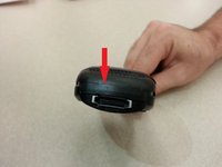
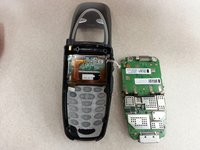
    • Push the tab located at the bottom of the battery towards the top of the phone.

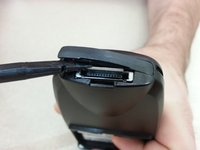
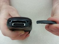
    • Lift the battery away from the phone.

  2. Motorola i1000plus Keypad Circuit Board Replacement, Antenna: step 2, image 1 of 3 Motorola i1000plus Keypad Circuit Board Replacement, Antenna: step 2, image 2 of 3 Motorola i1000plus Keypad Circuit Board Replacement, Antenna: step 2, image 3 of 3
    • Grasp the antenna between two fingers and turn it counterclockwise until it is unscrewed.

    • Pull the antenna straight out of the phone.

  3. Motorola i1000plus Keypad Circuit Board Replacement, Back Cover: step 3, image 1 of 3 Motorola i1000plus Keypad Circuit Board Replacement, Back Cover: step 3, image 2 of 3 Motorola i1000plus Keypad Circuit Board Replacement, Back Cover: step 3, image 3 of 3
    • Pry off the bottom piece using the spudger.

    • There are notches on the edge of this piece that can be used to aid prying.

  4. Motorola i1000plus Keypad Circuit Board Replacement: step 4, image 1 of 1
    • Remove the sticker overlaying the NEXTEL logo.

  5. Motorola i1000plus Keypad Circuit Board Replacement: step 5, image 1 of 1
    • Using a Torx T8 screwdriver, remove the two screws exposed after removing the sticker by unscrewing counterclockwise.

  6. Motorola i1000plus Keypad Circuit Board Replacement: step 6, image 1 of 3 Motorola i1000plus Keypad Circuit Board Replacement: step 6, image 2 of 3 Motorola i1000plus Keypad Circuit Board Replacement: step 6, image 3 of 3
    • Starting from the bottom and working towards the top, use a spudger to pry the back cover off the phone.

  7. Motorola i1000plus Keypad Circuit Board Replacement, Motherboard: step 7, image 1 of 1
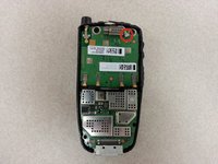
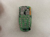
    • Using a Torx T8 screwdriver, remove the two circled screws by unscrewing counterclockwise.

  8. Motorola i1000plus Keypad Circuit Board Replacement: step 8, image 1 of 3 Motorola i1000plus Keypad Circuit Board Replacement: step 8, image 2 of 3 Motorola i1000plus Keypad Circuit Board Replacement: step 8, image 3 of 3
    • Using a pair of tweezers, firmly grasp the connector at the top of the phone and pull the connector straight away from the phone.

    • Do not pull the connector off by the wire. This could damage or destroy the wire or connector.

  9. Motorola i1000plus Keypad Circuit Board Replacement: step 9, image 1 of 2 Motorola i1000plus Keypad Circuit Board Replacement: step 9, image 2 of 2
    • Unclip the ribbon cable, located underneath the motherboard, by using the spudger to push up on the dark brown part of the connector located on the circuit board.

    • Do not pull the motherboard too far away from the phone with the ribbon cable still connected. this will damage the cable or the motherboard.

  10. Motorola i1000plus Keypad Circuit Board Replacement: step 10, image 1 of 2 Motorola i1000plus Keypad Circuit Board Replacement: step 10, image 2 of 2
    • Remove the motherboard by firmly grasping the edges of the circuit board with one hand and the phone with the other and pulling up on the motherboard slightly and then pulling it straight down toward the bottom of the phone.

    • Be sure to pull straight down to disconnect the ribbon cable properly. Pulling in another direction may cause damage to the cable or the motherboard.

  11. Motorola i1000plus Keypad Circuit Board Replacement, Keypad Circuit Board: step 11, image 1 of 3 Motorola i1000plus Keypad Circuit Board Replacement, Keypad Circuit Board: step 11, image 2 of 3 Motorola i1000plus Keypad Circuit Board Replacement, Keypad Circuit Board: step 11, image 3 of 3
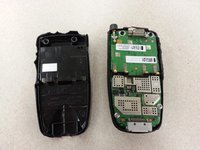
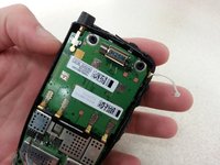
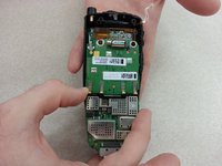
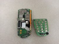
    • Flip the motherboard over 180 degrees.

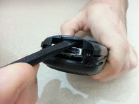
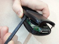
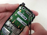
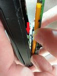
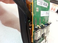
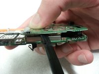
    • Place a spudger in between the gold plate and the bottom of the circuit board.

    • Carefully use the spudger as a prying tool to lift the circuit board from the motherboard.

    • Be very careful not to insert the spudger too far or to apply too much pressure. It can easily damage the circuit board.

Conclusion

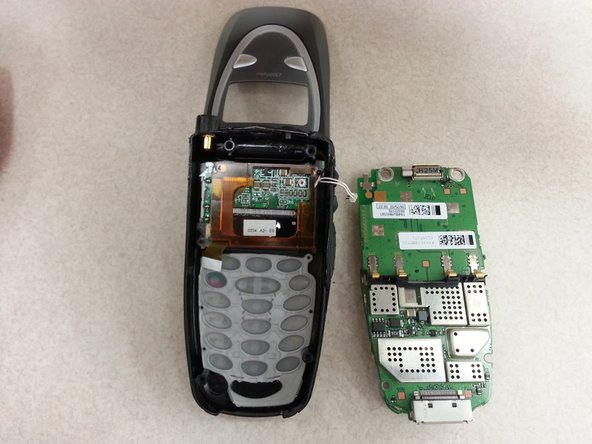
To reassemble your device, follow these instructions in reverse order.

Austin Lake

Member since: 10/18/13

501 Reputation

5 Guides authored

Team

Clemson, Team 13-3, Benson Fall 2013 Member of Clemson, Team 13-3, Benson Fall 2013

CLEM-BENSON-F13S13G3

3 Members

9 Guides authored

0 Comments

Add Comment

View Statistics:

Past 24 Hours: 0

Past 7 Days: 0

Past 30 Days: 1

All Time: 223