Free Shipping on Domestic Orders $75+

Motherboard Desoldering

Views: 241

View statistics:

Past 24 Hours:
1
Past 7 Days:
7
Past 30 Days:
16
All Time:
241
Comments: 11

11 comments on steps.

Completed: 0

No one has marked this guide "completed." Will you be the first?

Favorites: 0

No one has favorited (and subscribed to) this guide. Will you be the first?

Time Required: No estimate
Difficulty: Moderate
Motherboard Desoldering
Prerequisite Only This is a prerequisite-only guide! This guide is part of another procedure and isn’t meant to be used alone.

Introduction

Go to step 1 ↓

Follow this guide to desolder the motherboard from the vibration motors on your Sony DualSense controller.

This is a prerequisite-only guide! This guide is part of another procedure and isn't meant to be used alone.

What you need

Tools

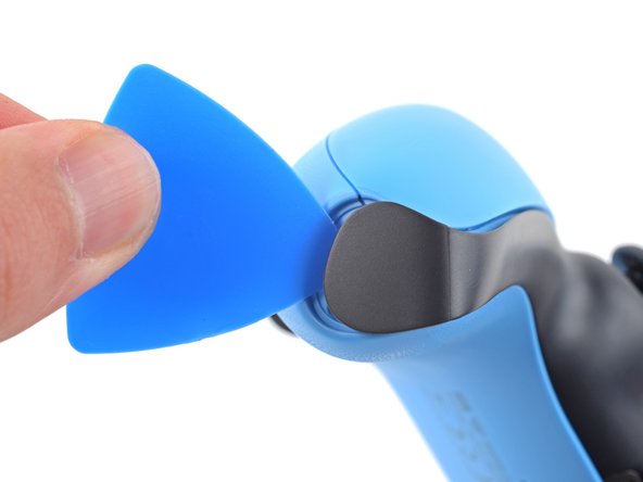
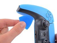
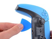
    1. Motherboard Desoldering, Unclip the right end of the middle trim: step 1, image 1 of 2 Motherboard Desoldering, Unclip the right end of the middle trim: step 1, image 2 of 2
      • Disconnect and power down the controller before you begin.

      • Insert an opening pick underneath the middle trim at the bottom-right corner of the controller to release the clips securing it to the case.

      Ask FixBot

      Add Comment

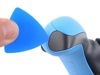
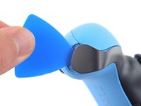
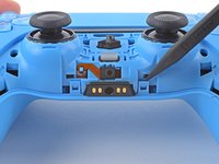
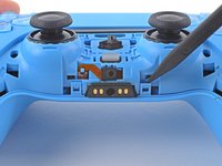
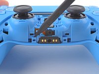
    2. Motherboard Desoldering, Unclip the lower-right edge of the middle trim: step 2, image 1 of 3 Motherboard Desoldering, Unclip the lower-right edge of the middle trim: step 2, image 2 of 3 Motherboard Desoldering, Unclip the lower-right edge of the middle trim: step 2, image 3 of 3
      • Slide the opening pick along the lower-right edge of the middle trim to release the clips securing it to the case.

      Ask FixBot

      Add Comment

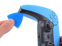
    3. Motherboard Desoldering, Unclip the left end of the middle trim: step 3, image 1 of 2 Motherboard Desoldering, Unclip the left end of the middle trim: step 3, image 2 of 2
      • Insert an opening pick underneath the middle trim at the bottom-left corner of the controller to release the clips securing it to the case.

      Ask FixBot

      Add Comment

    4. Motherboard Desoldering, Unclip the lower-left edge of the middle trim: step 4, image 1 of 3 Motherboard Desoldering, Unclip the lower-left edge of the middle trim: step 4, image 2 of 3 Motherboard Desoldering, Unclip the lower-left edge of the middle trim: step 4, image 3 of 3
      • Slide the opening pick along the lower-left edge of the middle trim to release the clips securing it to the case.

      Ask FixBot

      Add Comment

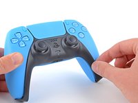
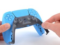
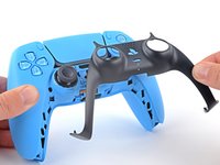
    5. Motherboard Desoldering, Remove the middle trim: step 5, image 1 of 3 Motherboard Desoldering, Remove the middle trim: step 5, image 2 of 3 Motherboard Desoldering, Remove the middle trim: step 5, image 3 of 3
      • Use your fingers to lift up the bottom edge of the middle trim to release the remaining clips.

      • Lift the middle trim over the joysticks to remove it.

      • During reassembly, position the middle trim into place and press along all edges to engage the clips securing it to the controller.

      Ask FixBot

      Add Comment

    1. Motherboard Desoldering, Remove the L1 button: step 6, image 1 of 3 Motherboard Desoldering, Remove the L1 button: step 6, image 2 of 3 Motherboard Desoldering, Remove the L1 button: step 6, image 3 of 3
      • Insert the flat end of a spudger into the gap above the L1 button.

      • Cover the button with your thumb to prevent it from ejecting across the room.

      • Pry the spudger upward to remove the L1 button.

      Ask FixBot

      Add Comment

    2. Motherboard Desoldering, Remove the R1 button: step 7, image 1 of 3 Motherboard Desoldering, Remove the R1 button: step 7, image 2 of 3 Motherboard Desoldering, Remove the R1 button: step 7, image 3 of 3
      • Insert the flat end of a spudger into the gap above the R1 button.

      • Cover the button with your thumb to prevent it from ejecting across the room.

      • Pry the spudger upward to remove the R1 button.

      Ask FixBot

      Add Comment

    1. Motherboard Desoldering, Remove the case screws: step 8, image 1 of 1
      • Use a Phillips screwdriver to remove the two 6.5 mm screws securing the bottom corners of the lower case.

      Ask FixBot

      Add Comment

    2. Motherboard Desoldering: step 9, image 1 of 1
      • Use a Phillips screwdriver to remove the two 6.5 mm screws behind the L1 and R1 buttons.

      Ask FixBot

      Add Comment

    3. Motherboard Desoldering, Unclip the rear case: step 10, image 1 of 3 Motherboard Desoldering, Unclip the rear case: step 10, image 2 of 3 Motherboard Desoldering, Unclip the rear case: step 10, image 3 of 3
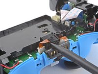
      • Use the pointed edge of a spudger to unclip the two clips on either side of the headset jack.

      Ask FixBot

      Add Comment

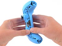
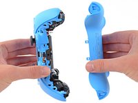
    4. Motherboard Desoldering, Remove the rear case: step 11, image 1 of 2 Motherboard Desoldering, Remove the rear case: step 11, image 2 of 2
      • Use your hands to carefully pull the rear case off of the controller.

      • During reassembly, make sure the red and black vibration motor wires are not pinched between the front and rear case.

      Ask FixBot

      Add Comment

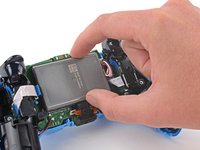
    1. Motherboard Desoldering, Reposition the battery: step 12, image 1 of 2 Motherboard Desoldering, Reposition the battery: step 12, image 2 of 2
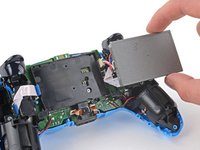
      • Lift the battery out of its bracket and reposition it to the right for better access to the battery connector.

      • Don't strain the battery cables.

      Ask FixBot

      Add Comment

    2. Motherboard Desoldering, Disconnect the battery: step 13, image 1 of 2 Motherboard Desoldering, Disconnect the battery: step 13, image 2 of 2
      Tool used on this step:
      Tweezers
      $4.99
      Buy
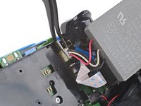
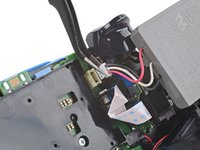
      • Use a pair of tweezers or your fingers to disconnect the battery from the motherboard.

      • Don't pull on the wires to disconnect the battery.

      Ask FixBot

      Add Comment

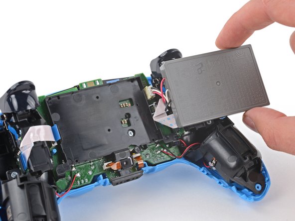
    3. Motherboard Desoldering, Remove the battery: step 14, image 1 of 1
      • Remove the battery.

      Ask FixBot

      Add Comment

    1. Motherboard Desoldering, Remove the lower microphone: step 15, image 1 of 2 Motherboard Desoldering, Remove the lower microphone: step 15, image 2 of 2
      • Use the pointed end of a spudger to remove the lower microphone from its bracket next to the battery.

      • During reassembly, make sure the end of the microphone's ribbon cable is slotted into the bracket.

      Ask FixBot

      Add Comment

    2. Motherboard Desoldering: step 16, image 1 of 2 Motherboard Desoldering: step 16, image 2 of 2
      Tool used on this step:
      Tweezers
      $4.99
      Buy
      • Grab the lower microphone ribbon cable pull tab with your fingers or a pair of tweezers and disconnect it from the motherboard.

      Ask FixBot

      Add Comment

    3. Motherboard Desoldering, Remove the battery bracket: step 17, image 1 of 1
      • Use a Phillips screwdriver to remove the 6.5 mm screw securing the battery bracket.

      Ask FixBot

      Add Comment

    4. Motherboard Desoldering: step 18, image 1 of 2 Motherboard Desoldering: step 18, image 2 of 2
      • Lift the battery bracket off of the motherboard.

      Ask FixBot

      Add Comment

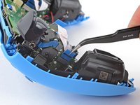
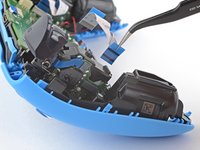
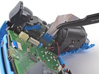
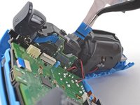
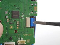
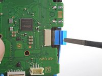
    5. Motherboard Desoldering, Disconnect the right trigger assembly: step 19, image 1 of 2 Motherboard Desoldering, Disconnect the right trigger assembly: step 19, image 2 of 2
      • Grip the right trigger assembly cable with a pair of tweezers or your fingers and disconnect it from the motherboard.

      • Use the pull tab to disconnect the cable. Don't pull on the cable itself.

      • Don't completely remove the ribbon cable yet.

      Ask FixBot

      Add Comment

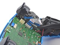
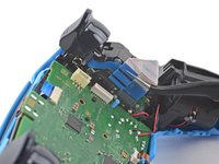
    6. Motherboard Desoldering: step 20, image 1 of 2 Motherboard Desoldering: step 20, image 2 of 2
      • Grip the right trigger assembly cable with a pair of tweezers or your fingers, and disconnect it from the trigger assembly.

      • Use the pull tab to disconnect the cable. Don't pull on the cable itself.

      • Depending on the controller's model, the ribbon cable may block the motherboard from coming loose. If so, remove the cable from the trigger assembly.

      Ask FixBot

      Add Comment

    7. Motherboard Desoldering, Disconnect the left trigger assembly: step 21, image 1 of 2 Motherboard Desoldering, Disconnect the left trigger assembly: step 21, image 2 of 2
      • Grip the left trigger assembly cable with a pair of tweezers or your fingers to disconnect it from the motherboard.

      • Use the pull tab to disconnect the cable. Don't pull on the cable itself.

      • Don't completely remove the ribbon cable yet.

      Ask FixBot

      Add Comment

    8. Motherboard Desoldering: step 22, image 1 of 2 Motherboard Desoldering: step 22, image 2 of 2
      • Grip the left trigger assembly cable with a pair of tweezers or your fingers to disconnect it from the trigger assembly.

      • Use the pull tab to disconnect the cable. Don't pull on the cable itself.

      • Depending on the controller's model, the ribbon cable may block the motherboard from coming loose. If so, remove the cable from the trigger assembly.

      Ask FixBot

      Add Comment

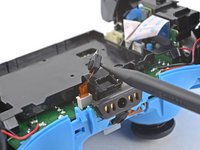
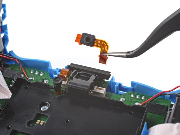
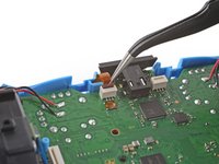
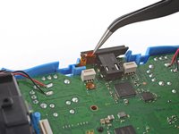
    9. Motherboard Desoldering, Disconnect the upper microphone: step 23, image 1 of 2 Motherboard Desoldering, Disconnect the upper microphone: step 23, image 2 of 2
      • Use a pair of tweezers or your fingers to disconnect the upper microphone from the motherboard.

      • Use the pull tab to disconnect the cable. Don't pull on the cable itself.

      • If you're not replacing this microphone, don't remove it from the frame.

      Ask FixBot

      Add Comment

    10. Motherboard Desoldering, Disconnect the touchpad: step 24, image 1 of 2 Motherboard Desoldering, Disconnect the touchpad: step 24, image 2 of 2
      • Use a pair of tweezers or your fingers to disconnect the touchpad cable from the motherboard.

      • Use the pull tab to disconnect the cable. Don't pull on the cable itself.

      Ask FixBot

      Add Comment

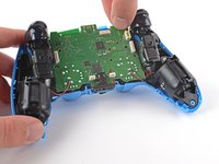
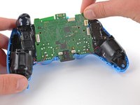
    11. Motherboard Desoldering, Lift out the motherboard: step 25, image 1 of 3 Motherboard Desoldering, Lift out the motherboard: step 25, image 2 of 3 Motherboard Desoldering, Lift out the motherboard: step 25, image 3 of 3
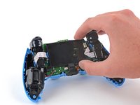
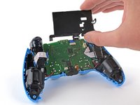
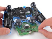
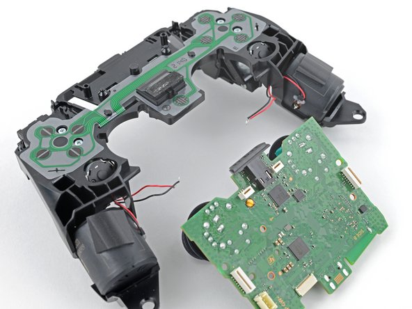
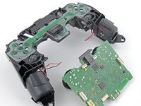
      • Carefully guide the joysticks through the front case and lift the motherboard out.

      • Don't strain the four soldered wires tethering the motherboard to the vibration motors.

      Ask FixBot

      Add Comment

    1. Motherboard Desoldering, Desolder the vibration motor wires: step 26, image 1 of 3 Motherboard Desoldering, Desolder the vibration motor wires: step 26, image 2 of 3 Motherboard Desoldering, Desolder the vibration motor wires: step 26, image 3 of 3
      Tool used on this step:
      FixHub Smart Soldering Iron
      $79.95
      Buy
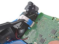
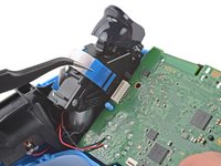
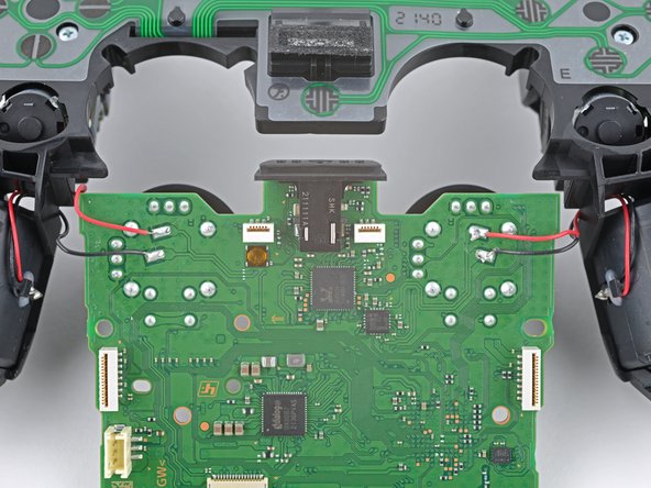
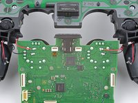
      • Flip the motherboard and midframe over to access the red and black vibration motor wires.

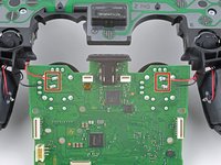
      • Use a soldering iron to disconnect the vibration motor wires from the motherboard.

      • To learn how to solder, or to get some helpful tips and tricks, check out our soldering guide.

      • During reassembly, refer to this photo to ensure the wires are soldered back to their correct positions.

      Ask FixBot

      Add Comment

Conclusion

To reassemble your device, follow these instructions in reverse order.

Cancel: I did not complete this guide.

Sam Omiotek

Member since: 02/25/19

100,996 Reputation

289 Guides authored

0 Guide Comments

Add Comment

View Statistics:

Past 24 Hours: 1

Past 7 Days: 7

Past 30 Days: 16

All Time: 241