This translation was generated by a machine and has not been reviewed by a person yet. Speak this language? Review it.
Introduction
This product series is very easy to repair. While a faulty main PCB used to be a reason to scrap the appliance, you can now find very affordable modules from salvaged machines on the used market.
Some people also attempt to repair the PCB themselves. Frequently replaced components include electrolytic capacitors, a diode, the bridge rectifier, and a transformer that generates low voltage for the ICs. However, this requires significant expertise in electronics and is not described here.
What you need
-
-
-
Open the lid (see separate guide). This is not strictly necessary, but it helps to ensure that no cables are pinched during reassembly
-
Pull the knob off by wiggling it forward with your hand
-
Using a sharp putty knife, insert it horizontally into one side of the plexiglass cover, and carefully twist the knife upward. Gently pry the plexiglass forward. Repeat this at several points until the cover can be pulled away upward.
-
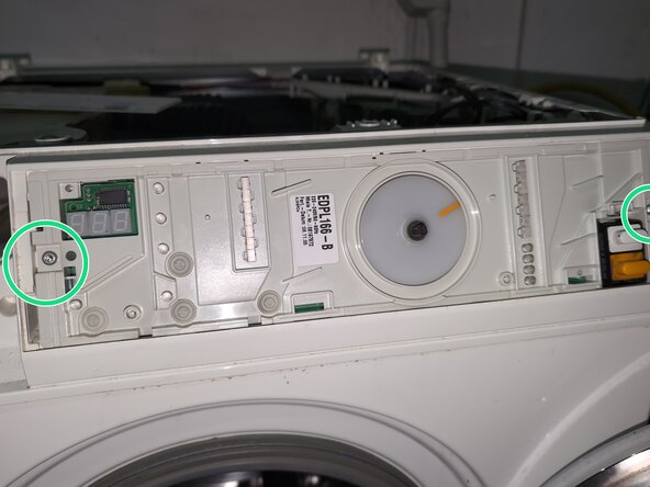
Release the T20 Torx screw on the left and right
-
The control unit can then be pulled out. Unplug the hose for the force sensitive squeeze button
 Ask FixBot
-
-
-
Pressing this retaining tab releases the main switch, which can then be pulled down slightly. There is a small plastic cap over the main switch terminals on the underside that can be easily removed.
-
Check once more that the power plug is disconnected, then unplug the brown power supply cable and the black power supply for the PCB from the main switch.
-
Afterwards, the main switch can be slid downwards. From below, unplug the door opener connector to the left of the switch PCB.
-
-
-
-
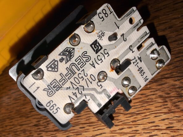
If the household washing machine was not functioning, be sure to test the switch with a multimeter. When switched off, all sockets must have high resistance relative to one another.
-
When the white 'On' switch is pressed (it must be a latching switch), socket 1 should have low resistance to socket 3, and socket 2 should have low resistance to socket 4.
-
When the orange door release button is pressed (momentary), there must be low resistance between socket 4 and socket 5.
-
On the other side of the switch, there is also a 6.3A fuse. Check for continuity.
-
-
-
Do not rely on Poka-Yoke—take a photo.
-
The cables can be unplugged without tools. Carefully remove the cables from the cable guides.
-
The control unit's part number is already visible without removal. Using the part number EDPL166-B, you can find spare parts on the used market. I had a W3441 with this control unit.
-
There is also an EDPL162-B, which likely fits the W3245; feel free to write further connections in the comments. The 162-B is still available new from Miele itself (as of 03/2026), while the 166-B is not offered there.
-
-
-
Wiggle the program display disk upward to unplug it. The axle is flattened, so the orientation cannot be lost.
-
The plastic housing has a few locking tabs that can be carefully loosened.
-
Remove the adhesive strip on the side.
-
The PCB is labeled EDPL100 and visually appears the same for various modules. However, it is likely programmed differently.
-
-





Follow the steps in reverse order to reassemble your device.