
MacBook Pro 13" Retina Display Late 2012 Logic Board Replacement

What you need

  1. MacBook Pro 13" Retina Display Late 2012 Logic Board Replacement, Lower Case: step 1, image 1 of 1
    Tool used on this step:
    Magnetic Project Mat
    $19.95
    Buy
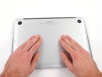
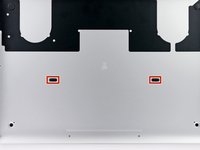
    • Remove the following ten screws securing the lower case to the upper case:

    • Two 2.3 mm P5 Pentalobe screws

    • Eight 3.0 mm P5 Pentalobe screws

    • Throughout this repair, keep track of each screw and make sure it goes back exactly where it came from to avoid damaging your device.

  2. MacBook Pro 13" Retina Display Late 2012 Logic Board Replacement: step 2, image 1 of 1
    • Wedge your fingers between the upper case and the lower case.

    • Gently pull the lower case away from the upper case.

    • Remove the lower case and set it aside.

  3. MacBook Pro 13" Retina Display Late 2012 Logic Board Replacement: step 3, image 1 of 3 MacBook Pro 13" Retina Display Late 2012 Logic Board Replacement: step 3, image 2 of 3 MacBook Pro 13" Retina Display Late 2012 Logic Board Replacement: step 3, image 3 of 3
    • During reassembly, gently push down the center of the lower case to reattach the two plastic clips.

    • The lower case is connected to the upper case at the center, with two plastic clips.

  4. MacBook Pro 13" Retina Display Late 2012 Logic Board Replacement, Battery Connector: step 4, image 1 of 1
    • Remove the plastic cover adhered to the battery contact board.

  5. MacBook Pro 13" Retina Display Late 2012 Logic Board Replacement: step 5, image 1 of 1
    • Remove the following screws securing the battery connector board to the logic board:

    • Two 2.8 mm T6 Torx screws

    • One 7.0 mm T6 Torx shouldered screw

  6. MacBook Pro 13" Retina Display Late 2012 Logic Board Replacement: step 6, image 1 of 2 MacBook Pro 13" Retina Display Late 2012 Logic Board Replacement: step 6, image 2 of 2
    • Use tweezers to remove the small plastic cover located near the bottom right of the battery connector board.

  7. MacBook Pro 13" Retina Display Late 2012 Logic Board Replacement: step 7, image 1 of 1
    • Remove the wide head 6.4 mm T6 Torx screw securing the battery connector to the logic board assembly.

  8. MacBook Pro 13" Retina Display Late 2012 Logic Board Replacement: step 8, image 1 of 2 MacBook Pro 13" Retina Display Late 2012 Logic Board Replacement: step 8, image 2 of 2
    • Carefully lift the battery connector board up off the logic board.

    • It is recommended to bend the battery cables just slightly, to keep the board suspended up above the logic board and out of the way.

    • Do not fold the board completely over, or crease the cables, as this may damage the battery.

  9. MacBook Pro 13" Retina Display Late 2012 Logic Board Replacement, Battery Contact Board: step 9, image 1 of 2 MacBook Pro 13" Retina Display Late 2012 Logic Board Replacement, Battery Contact Board: step 9, image 2 of 2
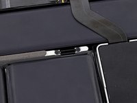
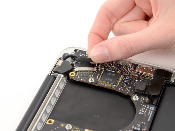
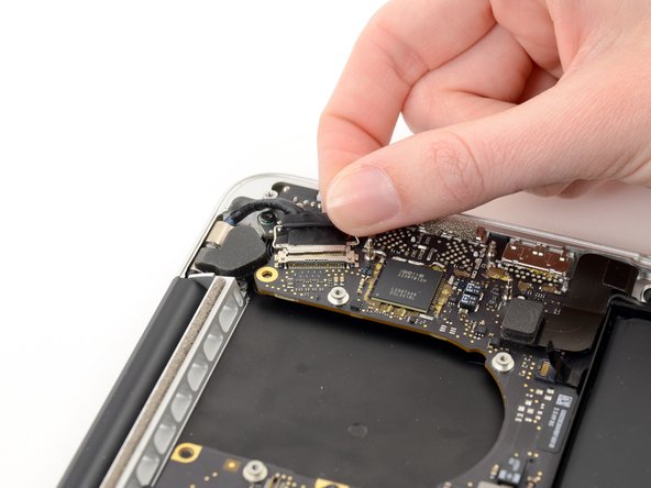
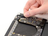
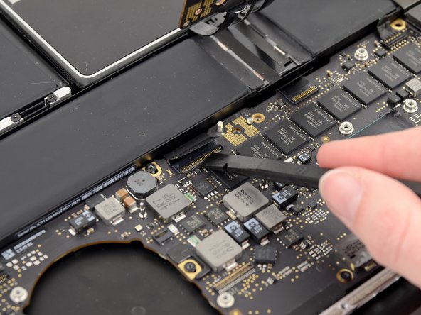
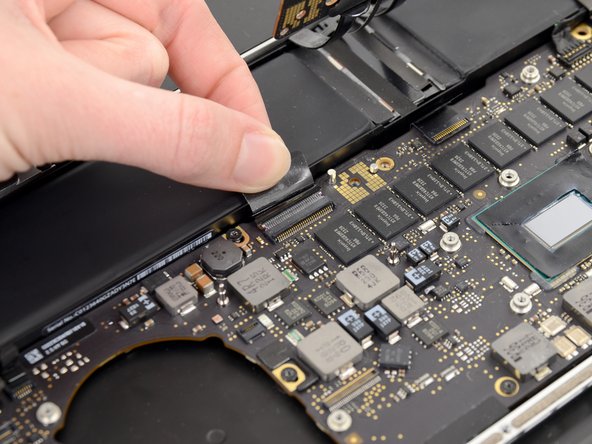
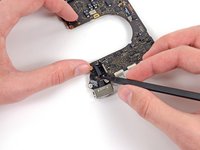
    • Grasp the Interposer with tweezers.

    • An interposer is the name for an interface that links one electrical connection to another. In this repair, it is the board connecting the battery to logic board.

    • Lift the Interposer off the logic board and remove it.

    • Removing this board will ensure that the battery remains disconnected throughout your repair, preventing your computer from accidentally powering on. It's also a good idea to take it out so it doesn't fall out unexpectedly.

  10. MacBook Pro 13" Retina Display Late 2012 Logic Board Replacement, Heat Sink Assembly: step 10, image 1 of 1
    • Remove the following screws securing the heat sink to the logic board assembly:

    • One 2.4 mm Phillips #00 screw

    • One 3.4 mm T5 Torx screw

    • Four 2.7 mm T5 Torx screws

  11. MacBook Pro 13" Retina Display Late 2012 Logic Board Replacement: step 11, image 1 of 2 MacBook Pro 13" Retina Display Late 2012 Logic Board Replacement: step 11, image 2 of 2
    • Lift and remove the heat sink up off the logic board assembly.

    • When reinstalling the heat sink, be sure to apply a new layer of thermal paste. If you have never applied thermal paste before, we have a guide that makes it easy.

  12. MacBook Pro 13" Retina Display Late 2012 Logic Board Replacement, I/O Board Data Cable: step 12, image 1 of 2 MacBook Pro 13" Retina Display Late 2012 Logic Board Replacement, I/O Board Data Cable: step 12, image 2 of 2
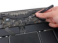
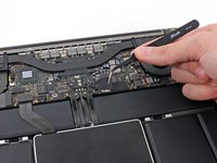
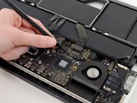
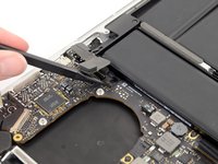
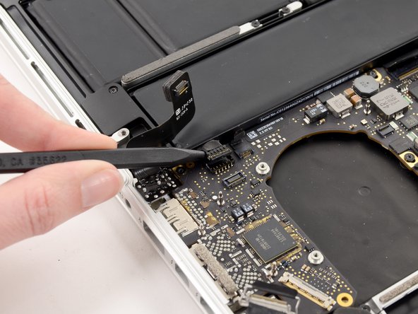
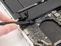
    • Use the flat end of a spudger to pry the right side of the I/O board data cable connector up off its socket on the I/O board.

    • When prying the I/O board data cable connector from its socket, make sure to pry the connector itself and not the socket. Prying the socket may cause irreversible damage to the I/O board.

  13. MacBook Pro 13" Retina Display Late 2012 Logic Board Replacement: step 13, image 1 of 2 MacBook Pro 13" Retina Display Late 2012 Logic Board Replacement: step 13, image 2 of 2
    • Wedge the flat end of a spudger beneath the left side of the I/O board data cable connector.

    • Gently twist the spudger to disconnect the I/O board data cable connector from its socket on the logic board.

  14. MacBook Pro 13" Retina Display Late 2012 Logic Board Replacement: step 14, image 1 of 1
    • Lift and remove the I/O board data cable from the MacBook Pro.

  15. MacBook Pro 13" Retina Display Late 2012 Logic Board Replacement, iSight Camera Cable: step 15, image 1 of 2 MacBook Pro 13" Retina Display Late 2012 Logic Board Replacement, iSight Camera Cable: step 15, image 2 of 2
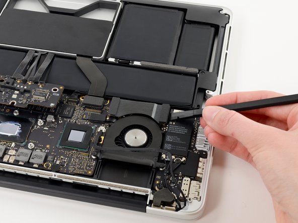
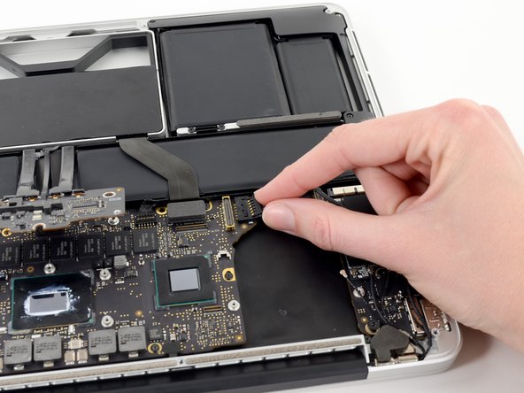
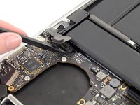
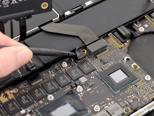
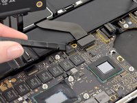
    • Use the tip of a spudger to push the iSight camera cable connector straight away from its socket on the logic board.

    • It is recommended to carefully push on both sides of the connector to "walk" it out of its socket.

  16. MacBook Pro 13" Retina Display Late 2012 Logic Board Replacement: step 16, image 1 of 2 MacBook Pro 13" Retina Display Late 2012 Logic Board Replacement: step 16, image 2 of 2
    • Move the iSight camera cable aside.

  17. MacBook Pro 13" Retina Display Late 2012 Logic Board Replacement, Right Fan: step 17, image 1 of 3 MacBook Pro 13" Retina Display Late 2012 Logic Board Replacement, Right Fan: step 17, image 2 of 3 MacBook Pro 13" Retina Display Late 2012 Logic Board Replacement, Right Fan: step 17, image 3 of 3
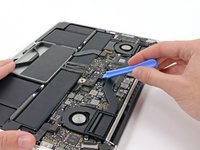
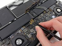
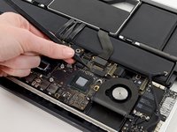
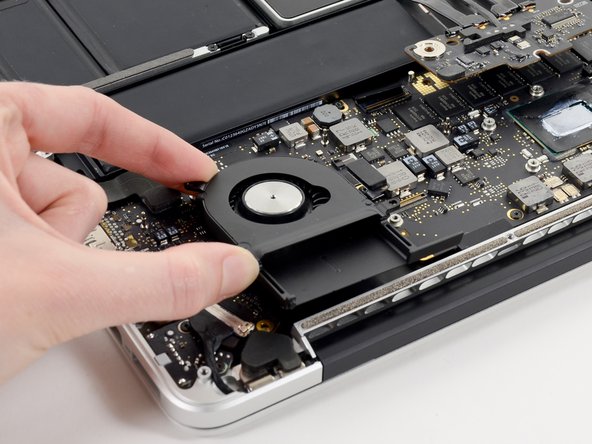
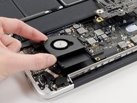
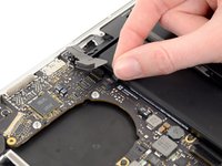
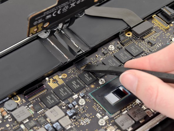
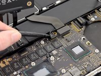
    • Use the tip of a spudger to flip up the retaining flap on the right fan ribbon cable ZIF socket.

    • Be sure you are prying up on the hinged retaining flap, not the socket itself.

    • Pull the right fan ribbon cable straight out of its socket on the logic board.

  18. MacBook Pro 13" Retina Display Late 2012 Logic Board Replacement: step 18, image 1 of 1
    • Remove the three 3.1 mm T5 Torx screws securing the right fan to the logic board assembly.

  19. MacBook Pro 13" Retina Display Late 2012 Logic Board Replacement: step 19, image 1 of 1
    • Lift and remove the right fan out of the upper case.

  20. MacBook Pro 13" Retina Display Late 2012 Logic Board Replacement, Left Fan: step 20, image 1 of 2 MacBook Pro 13" Retina Display Late 2012 Logic Board Replacement, Left Fan: step 20, image 2 of 2
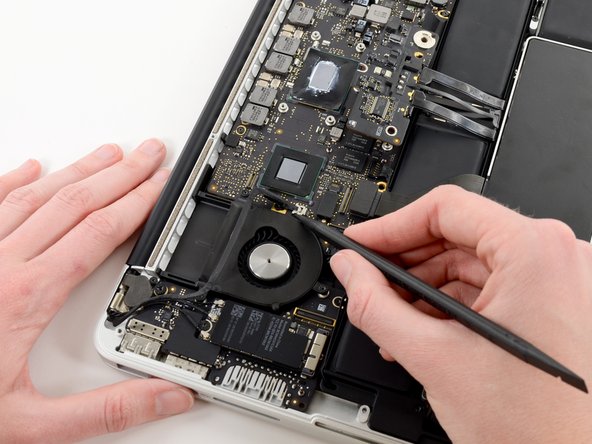
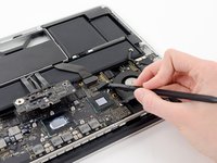
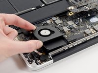
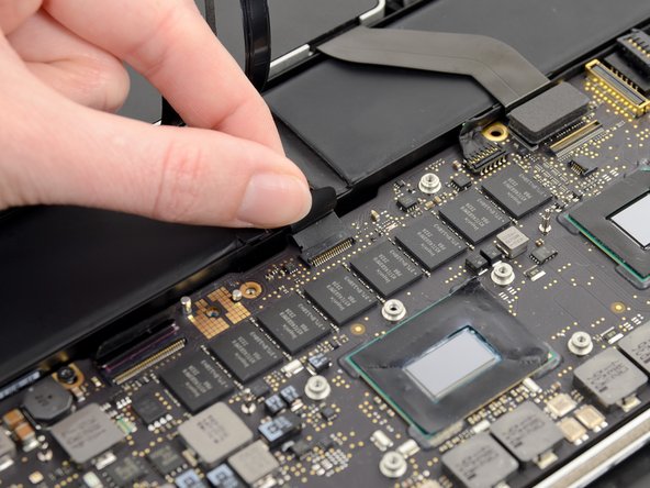
    • Use the tip of a spudger to flip up the retaining flap on the left fan ribbon cable ZIF socket.

    • Be sure you are prying up on the hinged retaining flap, not the socket itself.

  21. MacBook Pro 13" Retina Display Late 2012 Logic Board Replacement: step 21, image 1 of 1
    • Remove the three 3.1 mm T5 Torx screws securing the left fan to the logic board assembly.

  22. MacBook Pro 13" Retina Display Late 2012 Logic Board Replacement: step 22, image 1 of 2 MacBook Pro 13" Retina Display Late 2012 Logic Board Replacement: step 22, image 2 of 2
    • Lift and remove the left fan out of the upper case.

    • Make sure to pull the left fan straight away to simultaneously pull the left fan ribbon cable out of its socket on the logic board.

  23. MacBook Pro 13" Retina Display Late 2012 Logic Board Replacement, Logic Board Assembly: step 23, image 1 of 3 MacBook Pro 13" Retina Display Late 2012 Logic Board Replacement, Logic Board Assembly: step 23, image 2 of 3 MacBook Pro 13" Retina Display Late 2012 Logic Board Replacement, Logic Board Assembly: step 23, image 3 of 3
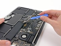
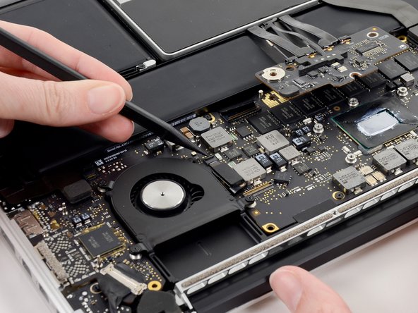
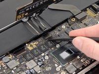
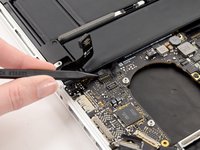
    • Use the tip of a spudger to push the edges of the I/O board connector straight out of its socket on the logic board.

    • It is recommended to carefully push on both sides of the connector to "walk" it out of its socket.

  24. MacBook Pro 13" Retina Display Late 2012 Logic Board Replacement: step 24, image 1 of 2 MacBook Pro 13" Retina Display Late 2012 Logic Board Replacement: step 24, image 2 of 2
    • Wedge the flat end of a spudger underneath the keyboard backlight connector and the logic board.

    • Gently twist the flat end of a spudger upwards to pry the keyboard backlight connector up off its socket on the logic board.

  25. MacBook Pro 13" Retina Display Late 2012 Logic Board Replacement: step 25, image 1 of 3 MacBook Pro 13" Retina Display Late 2012 Logic Board Replacement: step 25, image 2 of 3 MacBook Pro 13" Retina Display Late 2012 Logic Board Replacement: step 25, image 3 of 3
    • Grab the black pull tab secured to the display data cable lock and rotate it toward the DC-In side of the computer.

    • Pull the display data cable straight out of its socket on the logic board.

    • Do not lift up on the display data cable, as its socket is very fragile. Pull the cable parallel to the face of the logic board.

  26. MacBook Pro 13" Retina Display Late 2012 Logic Board Replacement: step 26, image 1 of 1
    • Pry the headphone jack cable connector up off its socket on the logic board.

  27. MacBook Pro 13" Retina Display Late 2012 Logic Board Replacement: step 27, image 1 of 3 MacBook Pro 13" Retina Display Late 2012 Logic Board Replacement: step 27, image 2 of 3 MacBook Pro 13" Retina Display Late 2012 Logic Board Replacement: step 27, image 3 of 3
    • Use the tip of a spudger to flip up the retaining flap on the microphone ribbon cable ZIF socket.

    • Be sure you are prying up on the hinged retaining flap, not the socket itself.

    • Grasp the plastic pull tab and pull the microphone ribbon cable out of its socket.

  28. MacBook Pro 13" Retina Display Late 2012 Logic Board Replacement: step 28, image 1 of 3 MacBook Pro 13" Retina Display Late 2012 Logic Board Replacement: step 28, image 2 of 3 MacBook Pro 13" Retina Display Late 2012 Logic Board Replacement: step 28, image 3 of 3
    • Use the flat edge of a spudger to flip up the retaining flap on the keyboard ribbon cable ZIF socket.

    • Be sure you are prying up on the hinged retaining flap, not the socket itself.

    • Grasp the plastic pull tab and pull the keyboard ribbon cable out of its socket.

  29. MacBook Pro 13" Retina Display Late 2012 Logic Board Replacement: step 29, image 1 of 3 MacBook Pro 13" Retina Display Late 2012 Logic Board Replacement: step 29, image 2 of 3 MacBook Pro 13" Retina Display Late 2012 Logic Board Replacement: step 29, image 3 of 3
    • Repeat the previous procedure to disconnect the Trackpad ribbon cable from its socket on the logic board.

  30. MacBook Pro 13" Retina Display Late 2012 Logic Board Replacement: step 30, image 1 of 2 MacBook Pro 13" Retina Display Late 2012 Logic Board Replacement: step 30, image 2 of 2
    • Wedge the flat end of a spudger beneath the right speaker cable connector.

    • Gently pry the right speaker cable connector up off from its socket on the logic board.

    • Be sure you are prying up on the connector, not the socket itself.

  31. MacBook Pro 13" Retina Display Late 2012 Logic Board Replacement: step 31, image 1 of 1
    • Use the flat end of a spudger to pry the SSD cable connector up off its socket on the logic board.

  32. MacBook Pro 13" Retina Display Late 2012 Logic Board Replacement: step 32, image 1 of 2 MacBook Pro 13" Retina Display Late 2012 Logic Board Replacement: step 32, image 2 of 2
    • Wedge the tip of a spudger beneath the left speaker cable connector.

    • Gently pry the left speaker cable connector up off from its socket on the logic board.

    • Be sure you are prying up on the connector, not the socket itself.

  33. MacBook Pro 13" Retina Display Late 2012 Logic Board Replacement: step 33, image 1 of 1
    • Remove the nine 3.3 mm T5 Torx screws securing the logic board and MagSafe DC-in board to the upper case.

  34. MacBook Pro 13" Retina Display Late 2012 Logic Board Replacement: step 34, image 1 of 2 MacBook Pro 13" Retina Display Late 2012 Logic Board Replacement: step 34, image 2 of 2
    • Carefully grasp the corner of the logic board (opposite of the I/O ports) and lift the logic board out of the upper case.

  35. MacBook Pro 13" Retina Display Late 2012 Logic Board Replacement, MagSafe DC-In Board: step 35, image 1 of 2 MacBook Pro 13" Retina Display Late 2012 Logic Board Replacement, MagSafe DC-In Board: step 35, image 2 of 2
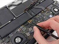
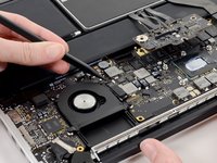
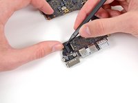
    • Gently push the edges of the MagSafe cable connector away from its socket on the logic board.

    • It is recommended "walk" the connector out of its socket. Simply push the top and bottom corners of the connector and carefully "walk it out" of its socket.

  36. MacBook Pro 13" Retina Display Late 2012 Logic Board Replacement: step 36, image 1 of 1
    • Pull the MagSafe cable connector straight out of its socket on the logic board.

  37. MacBook Pro 13" Retina Display Late 2012 Logic Board Replacement, Logic Board: step 37, image 1 of 1
    • Logic board remains.

Conclusion

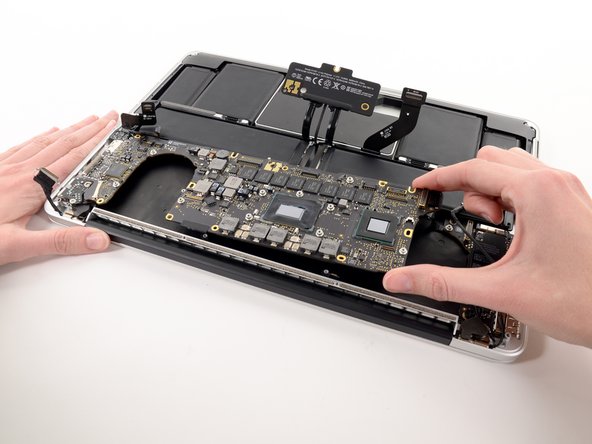
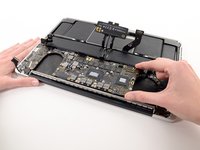
To reassemble your device, follow these instructions in reverse order.

31 other people completed this guide.

One Comment

NOTE: The logic boards you are placing into your Macbook Pro as a replacement probably are not coming from systems that are current and actively being used (they may have been on the shelf for a while)…more importantly they are almost certainly not coming from systems that were fully updated and running MacOS High Sierra. Realize that if you have updated your Macbook and are running High Sierra, your hard drive has been converted to the latest APFS Apple file system. In order for an older logic board to be able to read any of your APFS hard drive will require that the logic board gets the latest SMC/firmware updates. Without this you will not be able to boot from your hard drive. See how I was able to correct this dilemma here: Hard Drive/OS not recognized after logic board replacement

TimD - Reply

Add Comment

View Statistics:

Past 24 Hours: 3

Past 7 Days: 18

Past 30 Days: 74

All Time: 26,519