
MacBook Pro 13" Retina Display Early 2015 Logic Board Assembly Replacement

Prerequisite Only
This guide is only intended to be used as a prerequisite for other guides. It's incomplete by itself.

What you need

  1. MacBook Pro 13" Retina Display Early 2015 Logic Board Assembly Replacement, Logic Board Assembly: step 1, image 1 of 2 MacBook Pro 13" Retina Display Early 2015 Logic Board Assembly Replacement, Logic Board Assembly: step 1, image 2 of 2
    • Remove the two 2.1 mm T5 Torx screws securing the I/O board cable bracket to the logic board.

    • Remove the I/O board cable bracket.

  2. MacBook Pro 13" Retina Display Early 2015 Logic Board Assembly Replacement: step 2, image 1 of 2 MacBook Pro 13" Retina Display Early 2015 Logic Board Assembly Replacement: step 2, image 2 of 2
    • Use the flat end of a spudger to pop the I/O board connector straight up off its socket on the logic board.

    • Be careful to only pry up on the I/O board cable, not on the socket itself or you risk damaging your logic board.

  3. MacBook Pro 13" Retina Display Early 2015 Logic Board Assembly Replacement: step 3, image 1 of 2 MacBook Pro 13" Retina Display Early 2015 Logic Board Assembly Replacement: step 3, image 2 of 2
    • Lift the logic board end of the I/O board cable straight up to bend it out of the way.

    • To avoid damage to the cable, fold only at the bend in the I/O board end of the cable.

  4. MacBook Pro 13" Retina Display Early 2015 Logic Board Assembly Replacement: step 4, image 1 of 2 MacBook Pro 13" Retina Display Early 2015 Logic Board Assembly Replacement: step 4, image 2 of 2
    • Use the tip of a spudger to lift the right speaker connector straight up out of its socket on the logic board.

  5. MacBook Pro 13" Retina Display Early 2015 Logic Board Assembly Replacement: step 5, image 1 of 2 MacBook Pro 13" Retina Display Early 2015 Logic Board Assembly Replacement: step 5, image 2 of 2
    • With the tip of a spudger, push on either side of the I/O board connector to walk it out of its socket on the logic board.

  6. MacBook Pro 13" Retina Display Early 2015 Logic Board Assembly Replacement: step 6, image 1 of 3 MacBook Pro 13" Retina Display Early 2015 Logic Board Assembly Replacement: step 6, image 2 of 3 MacBook Pro 13" Retina Display Early 2015 Logic Board Assembly Replacement: step 6, image 3 of 3
    • Use the flat end of a spudger to disconnect the keyboard backlight cable and bend it up out of the way of the logic board.

  7. MacBook Pro 13" Retina Display Early 2015 Logic Board Assembly Replacement: step 7, image 1 of 3 MacBook Pro 13" Retina Display Early 2015 Logic Board Assembly Replacement: step 7, image 2 of 3 MacBook Pro 13" Retina Display Early 2015 Logic Board Assembly Replacement: step 7, image 3 of 3
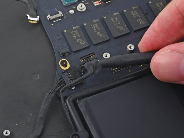
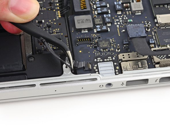
    • Grab the black plastic tab to flip the display cable connector open and pull it straight out of its socket on the logic board.

    In my 2015 retina MacBook Pro 13”: I saw as shown the piece of black plastic tape. One peels this off as shown, using the same tweezers shown, or something else. The tweezers shown work well to lift the stainless steel clip, again as shown. But I add here that the points of the ribbon cable to grab and pull horizontally back are not optimal, as shown. You do not have to grab the ribbon. There are two points where the wire clip attaches to the connector that work well as places to grab with the tweezers shown. Hope this is clear

    Thomas Sturgill - Reply

  8. MacBook Pro 13" Retina Display Early 2015 Logic Board Assembly Replacement: step 8, image 1 of 2 MacBook Pro 13" Retina Display Early 2015 Logic Board Assembly Replacement: step 8, image 2 of 2
    • Carefully pull the DC-In board connector straight out of its socket on the logic board.

  9. MacBook Pro 13" Retina Display Early 2015 Logic Board Assembly Replacement: step 9, image 1 of 3 MacBook Pro 13" Retina Display Early 2015 Logic Board Assembly Replacement: step 9, image 2 of 3 MacBook Pro 13" Retina Display Early 2015 Logic Board Assembly Replacement: step 9, image 3 of 3
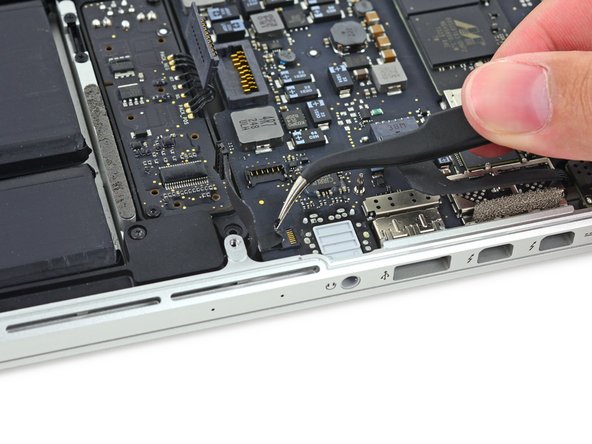
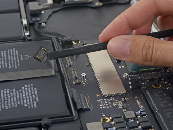
    • Wedge the flat end of a spudger under the left speaker cable near the connector and lift it straight up out of its socket and fold it out of the way.

    I wasn’t careful enough or something, the socket came straight off, ouch. I don’t even see how it was connected originally. Not soldered or anything, will try to solder myself but it looks very thin. Be careful!

    Ray Dai - Reply

  10. MacBook Pro 13" Retina Display Early 2015 Logic Board Assembly Replacement: step 10, image 1 of 2 MacBook Pro 13" Retina Display Early 2015 Logic Board Assembly Replacement: step 10, image 2 of 2
    • If necessary, peel back any tape covering the microphone cable ZIF connector.

  11. MacBook Pro 13" Retina Display Early 2015 Logic Board Assembly Replacement: step 11, image 1 of 3 MacBook Pro 13" Retina Display Early 2015 Logic Board Assembly Replacement: step 11, image 2 of 3 MacBook Pro 13" Retina Display Early 2015 Logic Board Assembly Replacement: step 11, image 3 of 3
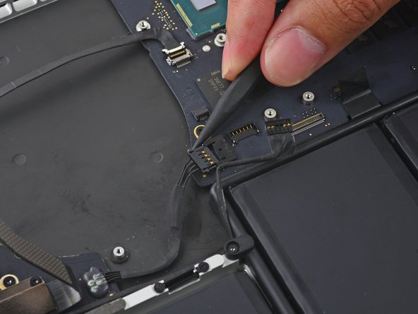
    • Use the tip of a spudger to flip the retaining tab on the microphone cable ZIF connector.

    • Pull the microphone cable out of its socket on the logic board.

    This tiny connector was difficult for me, and I hope I have not damaged it. Same design as some connectors already removed. A tiny, plastic front latch is lifted up, causing release. You grab the ribbon cable and pull it back horizontally, and to my surprise, this is end is just one tiny flat metal end, no multiple wire connectors that mate on the male end of the ribbon cable.

    Thomas Sturgill - Reply

  12. MacBook Pro 13" Retina Display Early 2015 Logic Board Assembly Replacement: step 12, image 1 of 3 MacBook Pro 13" Retina Display Early 2015 Logic Board Assembly Replacement: step 12, image 2 of 3 MacBook Pro 13" Retina Display Early 2015 Logic Board Assembly Replacement: step 12, image 3 of 3
    • If necessary, peel back any tape covering the keyboard cable connector.

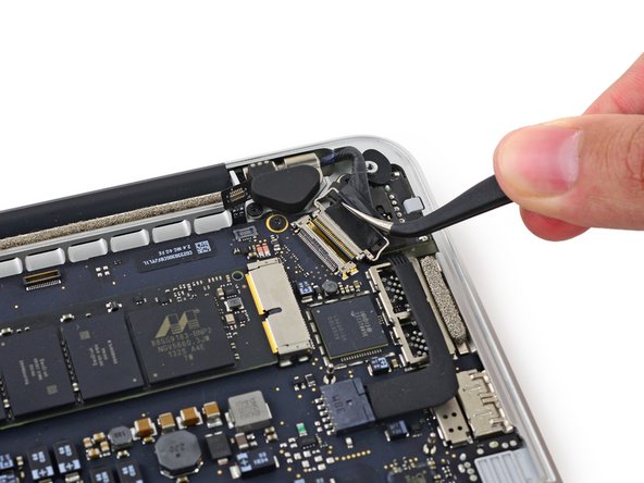
    • Use the tip of a spudger to flip the retaining tab on the ZIF connector.

    Also very difficult, because there is so little room to wriggle the ribbon cable, horizontally and backward. The photos do not offer a solution. The points I used are white (at least not black) points on the both, outer edges, and I was able to push there with the tip of the spudger.

    Thomas Sturgill - Reply

  13. MacBook Pro 13" Retina Display Early 2015 Logic Board Assembly Replacement: step 13, image 1 of 2 MacBook Pro 13" Retina Display Early 2015 Logic Board Assembly Replacement: step 13, image 2 of 2
    • Pull the keyboard cable straight out of its ZIF socket on the logic board.

  14. MacBook Pro 13" Retina Display Early 2015 Logic Board Assembly Replacement: step 14, image 1 of 3 MacBook Pro 13" Retina Display Early 2015 Logic Board Assembly Replacement: step 14, image 2 of 3 MacBook Pro 13" Retina Display Early 2015 Logic Board Assembly Replacement: step 14, image 3 of 3
    • Use the flat end of a spudger to pop the trackpad connector straight up off its socket on the logic board.

    • Fold the cable out back over the battery to clear the way for the logic board.

  15. MacBook Pro 13" Retina Display Early 2015 Logic Board Assembly Replacement: step 15, image 1 of 1
    • Remove the five 3.5 mm T5 Torx screws securing the logic board to the upper case.

    Il y en a une plus longue que les autres.

    Easy Repair - Reply

  16. MacBook Pro 13" Retina Display Early 2015 Logic Board Assembly Replacement: step 16, image 1 of 3 MacBook Pro 13" Retina Display Early 2015 Logic Board Assembly Replacement: step 16, image 2 of 3 MacBook Pro 13" Retina Display Early 2015 Logic Board Assembly Replacement: step 16, image 3 of 3
    • Lift the processor end of the logic board up slightly and pull it toward the fan recess to free the ports from the edge of the upper case.

    • Remove the logic board.

    It won't come off; help!

    Zelma Garza - Reply

    It seems to be stuck on the thunderbolt ports for me won’t come out

    Brendan O'Rourk - Reply

    i found that it was difficult to get the processor back inside correctly during reassembly. it might take a few tries, as there are small “bracket” type pieces on the underside of the i/o ports that may bend out of shape. use caution, be exceedingly gentle and patient, but don’t give up!

    Colleen V - Reply

Conclusion

To reassemble your device, follow these instructions in reverse order.

One other person completed this guide.

Sam Goldheart

Member since: 10/18/12

465,970 Reputation

538 Guides authored

Team

iFixit Member of iFixit

Staff

136 Members

17,299 Guides authored

0 Comments

Add Comment

View Statistics:

Past 24 Hours: 0

Past 7 Days: 2

Past 30 Days: 11

All Time: 186