Introduction
WARNING: This is a challenging repair, involving micro soldering, and cutting cables inside your macbook. Only attempt if you are sure that this is possible for you, or you have no other hope. This repair is a marathon, and can take many hours of very delicate surgical work (good practice for open heart probably)
What you need
-
-
-
Power on your Mac and launch Terminal.
-
Copy and paste the following command (or type it exactly) into Terminal:
-
sudo nvram AutoBoot=%00
-
Press [return]. If prompted, enter your administrator password and press [return] again. Note: Your return key may also be labeled ⏎ or "enter."
-
sudo nvram AutoBoot=%03
 Ask FixBot
-
-
-
-
Tool used on this step:Magnetic Project Mat$19.95
-
Use a P5 Pentalobe driver to remove the six screws securing the lower case:
-
Two 6.2 mm screws
-
Two 5.3 mm screws
-
Two 3.4 mm screws
-
-
-
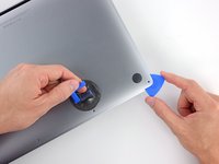
Apply a suction handle to the lower case near the front-center area of the MacBook Pro.
-
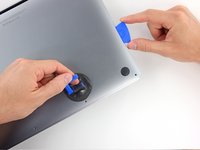
Lift the suction handle to create a slight separation between the lower case and the chassis.
-
-
-
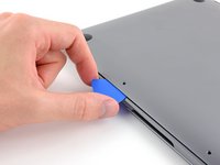
Insert one corner of an opening pick into the space between the lower case and the chassis.
-
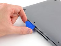
Slide the opening pick around the nearest corner and halfway up the side of the case.
-
-
-
Repeat the previous step on the opposite side, sliding your opening pick under the lower case and up the side to pop the second clip free.
-
-
-
Insert your opening pick once again under the front edge of the lower case, near one of the two centermost screw holes.
-
Give the pick a firm twist to pop free the third clip securing the lower case to the chassis.
-
Repeat this procedure near the other of the two centermost screw holes, popping the fourth clip free.
-
-
-
Pull the lower case firmly towards the front of the MacBook (away from the hinge area) to separate the last of the clips securing the lower case.
-
-
-
-
-
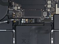
Carefully peel up the large piece of tape covering the battery connector, on the edge of the logic board nearest the battery.
-
Remove the tape.
-
-
-
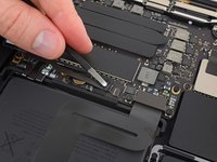
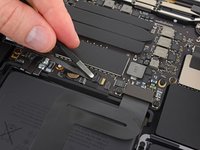
Gently peel back the small piece of tape covering the battery board data cable connector.
-
-
-
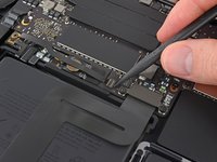
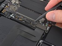
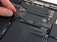
Use the tip of a spudger to flip up the small black locking tab securing the cable in its connector.
-
-
-
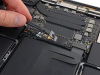
Disconnect the battery board data cable by sliding it out from its socket.
-
Slide parallel to the logic board, in the direction of the cable.
-
-
-
Use a T5 Torx driver to remove the 3.7 mm pancake screw securing the battery power connector.
-
-
-
Use a spudger to gently lift the battery power connector, disconnecting the battery.
-
Lift the connector high enough so that it stays separated from its socket. If it accidentally makes contact during the course of your repair, it could damage your MacBook Pro.
-
-
-
-
-
-
Remove the four 1.9 mm T3 Torx screws securing the plastic covers on top of the display hinges.
-
Remove both plastic hinge covers.
-
-
-
Remove the two 2.9 mm T3 Torx screws securing the aluminum cover on top of the main display cable.
-
Remove the cover.
-
-
-
Remove the two 1.7 mm T3 Torx screws securing the aluminum cover on top of the display cable flex connector.
-
Remove the cover.
-
-
-
Pry the display board flex cable straight up from its socket to disconnect it from the display board.
-
-
Tool used on this step:Tweezers$4.99
-
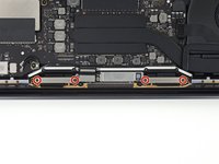
Remove the four 1.5 mm T3 Torx screws securing the two aluminum covers on top of the two display cables.
-
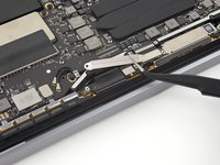
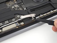
Use a pair of tweezers to remove the two aluminium covers.
-
-
-
Remove the two 3.3 mm T5 Torx screws (one from each side) securing the antenna cable assembly.
-
Also remove the two 4.1 mm T5 Torx screws (one from each side).
-
Remove the twelve 1.1 mm P2 pentalobe screws (six from each side) securing the rest of the antenna cable assembly.
-
-
-
Carefully disconnect the two antenna coax cables by prying them straight up from the logic board.
-
Slide your tweezers or spudger underneath each cable until it's near the socket, and then gently twist or pry up to disconnect it.
-
-
-
Remove the 2.8 mm T5 Torx screw securing the two antenna coax cables to the main board.
-
-
-
Use an opening pick to lever out the antenna cable assembly in the areas shown.
-
-
-
Carefully remove the antenna assembly, while simultaneously feeding the antenna cable bundle through the hole in the chassis.
-
-
-
-
-
Remove the four 3.9 mm T3 Torx screws securing the cover springs on the two display cables.
-
-
Tool used on this step:Tweezers$4.99
-
Grab the left side of the display cable assembly and pull it towards the bottom end of the MacBook and away from the cover spring.
-
Use a pair of tweezers to pull the cover spring on the display cable out of its recess.
-
Repeat this step with the right cover spring.
-
-
-
While steadying the MacBook pro with your free hand, remove the three T8 Torx screws from the lower display hinge.
-
Remove the remaining three T8 Torx screws from the upper display bracket.
-
-
-
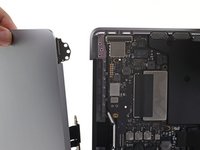
Push both halves of the MacBook Pro together so that the hinge brackets can be lifted clear of their recesses in the chassis.
-
Push the main body of the MacBook Pro away from you while pulling the screen toward you to separate it.
-
Remove the display/screen assembly, being careful not to snag it on any cables.
-
-
-
-
-
Identify the backlight flex cable and bend it looking for breaks
-
Breaks look like sharp bends in the cable - if unbroken, i should bend in a smooth arc
-
-
-
Cut the new cable so it can cover the distance past the break in the original cable
-
Add a few millimeters for buffer, and so that the final cable is 1.5-2mm longer than it was originally - this is the fix that future mac books used to prevent this issue in the first place
-
-
-
Tape the new cable, and begin to scrape off the solder mask
-
Use a hobby knife with a fresh blade, or a fiberglass pencil to expose a few mm of trace.
-
Using some light heat from a hot air gun can help with this step
-
-
-
Cut it just behind the break. Try and cut as straight as possible - this will allow the joint to be as clean and easy as possible.
-
Use a fresh razor blade, or utility blade to press straight down on the cable
-
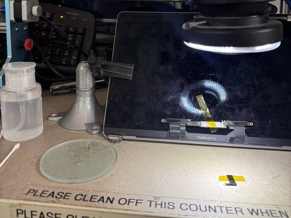
I have attached a picture of my setup, as it can be tricky to work on. Find something to sit under the cable - I used a 5mm glass plate
-
-
-
Same as the new cable, tape the cable down, and scrape away a few mm of solder mask.
-
Be gentle - and use heat if needed. this coating can be tough. A fiberglass pencil is highly recommended
-
-
-
Tape them down securely
-
Make sure that they are flat and clean
-
Green: Ground
-
Red: Power
-
Yellow: Signal (current return)
-
-
-
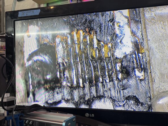
You don't need jumpers for the thicker traces, it is possible to gently flood them with solder, and bridge across
-
NOTE: Be quick with your iron, you don't want to melt the cable too bad - I set my iron to 450c and had the thinnest tip I could find in the lab.
-
The outermost traces are ground, the two thicker traces are backlight power and ground, and the thin traces are backlight return for current sensing
-
NOTE: it should work to bridge all the thinner cables together, but the backlight sensing will not work properly. I am not sure what the ramifications of this are but your backlight should still function.
-
-
-
Using a very fine un coated magnet wire, Affix one end to the old connector, and then bridge it down to the new connector.
-
I used the internal strands of a very fine multi strand wire, but this is not ideal. Ideally use pure copper magnet wire, as it will be the easiest to solder
-
Try not to put too much heat into the cables, just melt the solder you tinned onto the pads
-
-
-
Check for bridges with a multimeter in continuity mode
-
Trying to avoid bridging the power and ground - ultimately nothing should be bridged.
-
If a connection is bridged you can use solder wick to pull up some solder, and that may be enough to separate the traces
-
-
-
Using a silicone conformal coating, or any dielectric coating (I was in a pinch and only had access to a nail polish for this step - not ideal but works in a pinch) coat the connection and allow to dry.
-
Put on 2-3 coats on both sides
-
-


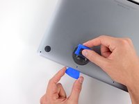
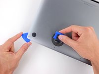
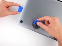


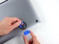


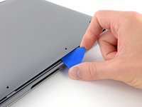


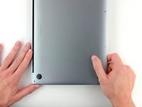
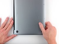
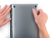


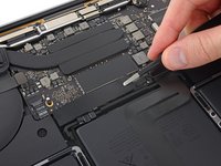
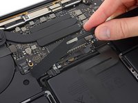


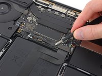
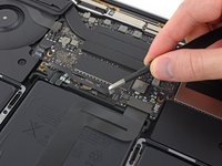










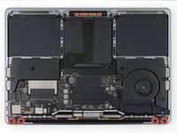
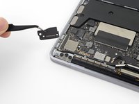
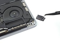


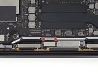
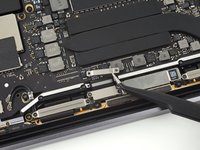


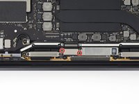
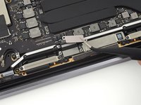


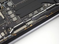
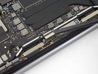




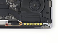


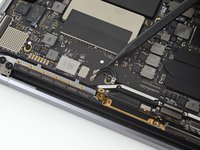
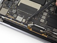
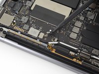


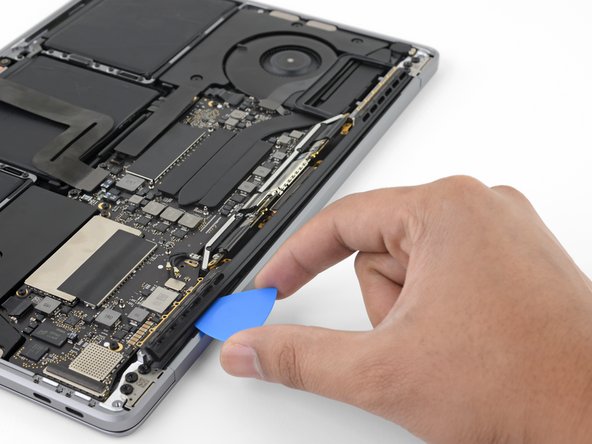

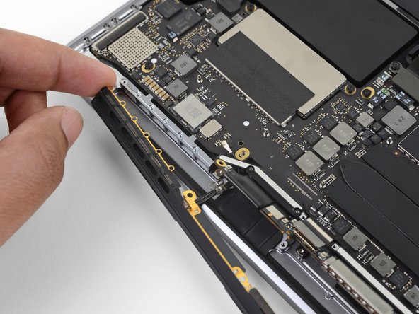



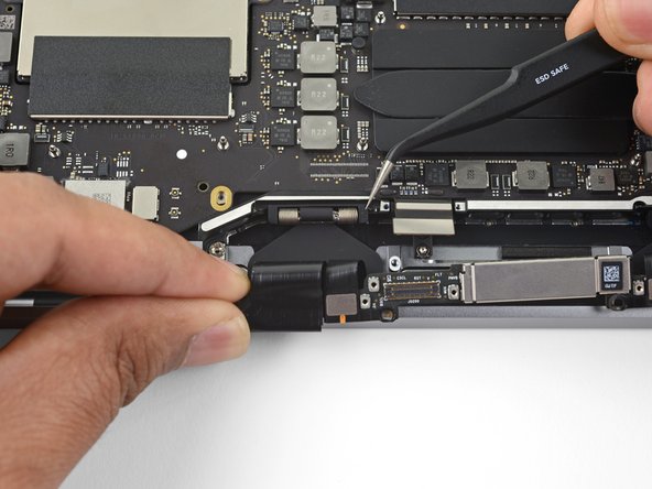



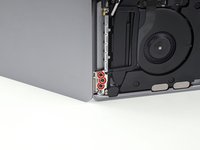
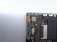


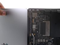
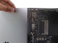





To reassemble your device, follow these instructions in reverse order.