
MacBook Air 13" Mid 2013 I/O Board Cable Replacement

What you need

  1. MacBook Air 13" Mid 2013 I/O Board Cable Replacement, Lower Case: step 1, image 1 of 1
    Tool used on this step:
    P5 Pentalobe Screwdriver Retina MacBook Pro and Air
    $5.99
    Buy
    • Before proceeding, power down your MacBook. Close the display and lay it on a soft surface, top-side down.

    • Use a P5 Pentalobe driver to remove ten screws securing the lower case, of the following lengths:

    • Two 9 mm screws

    • Eight 2.6 mm screws

  2. MacBook Air 13" Mid 2013 I/O Board Cable Replacement: step 2, image 1 of 1
    • Wedge your fingers between the display and the lower case and pull upward to pop the lower case off the Air.

    • Remove the lower case and set it aside.

  3. MacBook Air 13" Mid 2013 I/O Board Cable Replacement, Battery Connector: step 3, image 1 of 2 MacBook Air 13" Mid 2013 I/O Board Cable Replacement, Battery Connector: step 3, image 2 of 2
    • To ensure that everything is de-energized and won't turn on while you're working, it is recommended that you disconnect the battery.

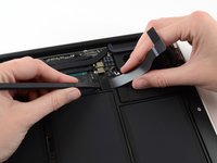
    • Grab the clear plastic pull tab attached to the battery connector and pull it parallel to the board toward the front edge of the Air.

    • Do not lift upward on the connector as you disconnect it or you risk damage to the connector socket.

  4. MacBook Air 13" Mid 2013 I/O Board Cable Replacement, I/O Board Cable: step 4, image 1 of 1
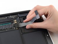
    • Use the flat end of a spudger to pry the I/O board cable connector up out of its socket on the I/O board.

  5. MacBook Air 13" Mid 2013 I/O Board Cable Replacement: step 5, image 1 of 1
    • Carefully peel the I/O board cable from the adhesive securing it to the top of the fan.

    • During reassembly, make sure this cable is in the correct orientation. It will fit if reversed, but the laptop will not boot.

  6. MacBook Air 13" Mid 2013 I/O Board Cable Replacement: step 6, image 1 of 2 MacBook Air 13" Mid 2013 I/O Board Cable Replacement: step 6, image 2 of 2
    • The following connector has an especially deep socket. Use care when disconnecting it.

    • While gently pulling the I/O board cable upward near its connection to the logic board, use the flat end of a spudger to pry up on alternating sides of the connector to help "walk" it out of its socket.

    • Remove the I/O board cable.

Conclusion

To reassemble your device, follow these instructions in reverse order.

7 other people completed this guide.

0 Comments

Add Comment

View Statistics:

Past 24 Hours: 0

Past 7 Days: 5

Past 30 Days: 21

All Time: 7,055