
Mac mini (PowerPC) Logic Board Replacement

What you need

  1. Mac mini (PowerPC) Logic Board Replacement, Top Housing: step 1, image 1 of 2 Mac mini (PowerPC) Logic Board Replacement, Top Housing: step 1, image 2 of 2
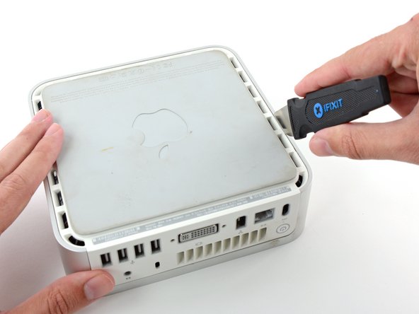
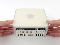
    • Power down your Mac mini, disconnect all of the cables, and flip it over.

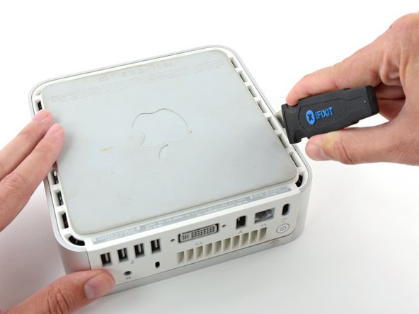
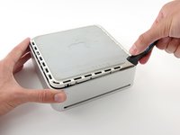
    • Insert the Jimmy into the crack between the aluminum top housing and the plastic lower housing.

    • The Jimmy should reach a stop about 3/8" down.

  2. Mac mini (PowerPC) Logic Board Replacement: step 2, image 1 of 3 Mac mini (PowerPC) Logic Board Replacement: step 2, image 2 of 3 Mac mini (PowerPC) Logic Board Replacement: step 2, image 3 of 3
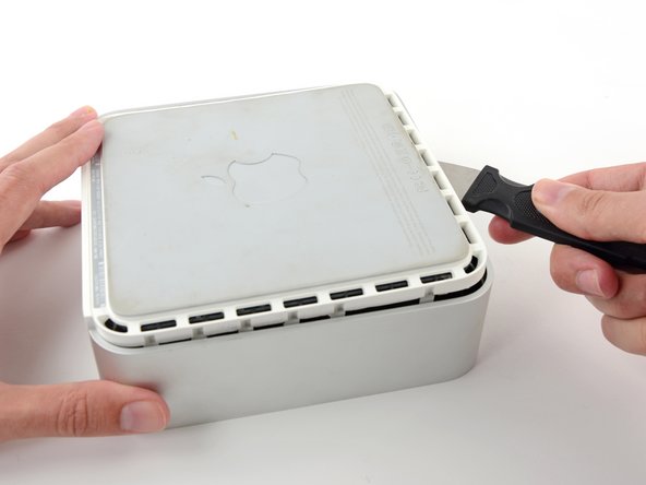
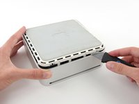
    • Gently bend the Jimmy outwards to pry the crack open a little larger and lift the lower housing up a small amount.

    • There are several plastic clips on the lower housing that fit into a channel in the aluminum top housing. Your goal is to use the Jimmy to push these clips inward enough to free them from the channel, while gently pulling up on the lower housing.

  3. Mac mini (PowerPC) Logic Board Replacement: step 3, image 1 of 2 Mac mini (PowerPC) Logic Board Replacement: step 3, image 2 of 2
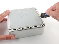
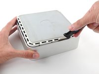
    • Once you have the first side free, rotate the Mac mini and start prying up on the front edge.

    • Use the same prying motion to both bend the clips inward and lift the lower housing up out of the top housing.

  4. Mac mini (PowerPC) Logic Board Replacement: step 4, image 1 of 2 Mac mini (PowerPC) Logic Board Replacement: step 4, image 2 of 2
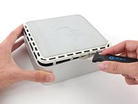
    • You may need to move the Jimmy along the edge to pry up all of the clips. Be patient and do a little bit at a time.

  5. Mac mini (PowerPC) Logic Board Replacement: step 5, image 1 of 2 Mac mini (PowerPC) Logic Board Replacement: step 5, image 2 of 2
    • Keep working around the perimeter, freeing the clips along the final edge.

  6. Mac mini (PowerPC) Logic Board Replacement: step 6, image 1 of 2 Mac mini (PowerPC) Logic Board Replacement: step 6, image 2 of 2
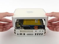
    • Flip the Mac mini back over and lift the top housing off of the lower housing.

  7. Mac mini (PowerPC) Logic Board Replacement, Mass Storage Unit: step 7, image 1 of 1
    • If your mini does not have Airport installed, then skip this step.

    • Grasp the Airport antenna board and lift it off of the two plastic posts holding it in place. You may need to push back the black plastic tab jutting through the lower left corner of the board.

  8. Mac mini (PowerPC) Logic Board Replacement: step 8, image 1 of 1
    • Remove the yellow tape securing the power button cable to the black plastic framework.

  9. Mac mini (PowerPC) Logic Board Replacement: step 9, image 1 of 1
    • Remove the three black Phillips screws securing the plastic framework to the logic board and lower case.

  10. Mac mini (PowerPC) Logic Board Replacement: step 10, image 1 of 1
    • Grasp the optical drive and mass storage unit in one hand and lift up enough so that you can see beneath it.

  11. Mac mini (PowerPC) Logic Board Replacement: step 11, image 1 of 1
    • If your mini has neither an Airport card nor a Bluetooth board, you can simply lift the optical drive up and away. Otherwise, you need to disconnect the Airport and/or Bluetooth antenna cables first.

    • With your free hand, pull the Bluetooth cable up from Bluetooth board and unplug the Airport antenna cable from the right of the Airport card. Caution: both of these connections are very small. When re-assembling unit after repair, you may want to remove the two screws holding the airport card to the assembly and lift the card up and out to re-attach the cables.

  12. Mac mini (PowerPC) Logic Board Replacement, Modem: step 12, image 1 of 1
    • Remove the two silver Phillips screws from the corners of the modem board.

  13. Mac mini (PowerPC) Logic Board Replacement: step 13, image 1 of 1
    • Pull the modem up from its connector. If it sticks, just wiggle it back and forth a bit as you pull up.

  14. Mac mini (PowerPC) Logic Board Replacement: step 14, image 1 of 1
    • Disconnect the RJ-11 cable from the back of the modem.

  15. Mac mini (PowerPC) Logic Board Replacement, Logic Board: step 15, image 1 of 1
    • Remove the two silver Phillips screws from the corners of the wireless interface board.

  16. Mac mini (PowerPC) Logic Board Replacement: step 16, image 1 of 1
    • Grasp the board at the front and back, and lift up on the front until the board pulls free of its connector.

  17. Mac mini (PowerPC) Logic Board Replacement: step 17, image 1 of 1
    • Pull back the black plastic latches on either end of the RAM chip.

  18. Mac mini (PowerPC) Logic Board Replacement: step 18, image 1 of 1
    • Grasp the RAM chip at the end opposite of the back ports, and pull directly up.

  19. Mac mini (PowerPC) Logic Board Replacement: step 19, image 1 of 1
    • Push the PRAM battery in and pull it up. You'll have to push the battery in further than you'd expect in order to get it to pop free.

    • When inserting the new battery, make sure the side with writing along the edges faces the black plastic holder. You should also insure that the metal connectors make contact with the battery (you can bend them forward if they do not).

  20. Mac mini (PowerPC) Logic Board Replacement: step 20, image 1 of 1
    • The cables you're about to remove are very fragile - do not pull directly on the wires. Instead, try to pry up the connector directly, using your fingernails or a small flathead screwdriver if necessary.

    • Disconnect the power button and sleep light cables from the logic board.

  21. Mac mini (PowerPC) Logic Board Replacement: step 21, image 1 of 1
    • Remove the single black Phillips screw from the front left corner of the logic board.

  22. Mac mini (PowerPC) Logic Board Replacement: step 22, image 1 of 1
    • Use one hand to slide a spudger underneath the logic board and the other to pull back on the black sleep light unit. Lift up the with the spudger to free the logic board from the lower case and use both hands to slide the logic board toward you.

Conclusion

To reassemble your device, follow these instructions in reverse order.

12 other people completed this guide.

Attached Documents

iRobot

Member since: 09/24/09

1 Reputation

636 Guides authored

3 Comments

Great guys thank you very much , there is some small diferences between this model vartiations but your guide is perfect

pcocaam - Reply

You are supposed to replace the heat transfer pad on the bottom case when you remove the logic board. If this pad doesn’t make good contact with the GPU, you’ll get overheating and the unit will goto sleep after a short time.

Al Hartman - Reply

My Mac Mini G4 is missing the screws for the HDD/DVD carrier and the one screw for the logic board. Can you tell me where I can buy these or give me specs so I can find replacements on eBay?

Al Hartman - Reply

Add Comment

View Statistics:

Past 24 Hours: 2

Past 7 Days: 9

Past 30 Days: 41

All Time: 23,122