
Kaffelogic Nano 7/LINK (D-P Serial) Mainboard Replacement

What you need

  1. Kaffelogic Nano 7/LINK (D-P Serial) Mainboard Replacement, Removing Front Panel Screws: step 1, image 1 of 2 Kaffelogic Nano 7/LINK (D-P Serial) Mainboard Replacement, Removing Front Panel Screws: step 1, image 2 of 2
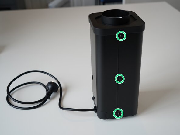
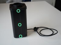
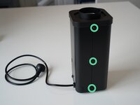
    • Remove the 6x 2.5mm Hex screws on the left and right side of the roaster.

    • Take care not to damage the buttons while maneuvering the front panel, with all six screws removed it may fall away.

  2. Kaffelogic Nano 7/LINK (D-P Serial) Mainboard Replacement, Lift the closure: step 2, image 1 of 2 Kaffelogic Nano 7/LINK (D-P Serial) Mainboard Replacement, Lift the closure: step 2, image 2 of 2
    • Hold the front panel steady while removing the plastic top/closure.

  3. Kaffelogic Nano 7/LINK (D-P Serial) Mainboard Replacement, Removing the front panel: step 3, image 1 of 1
    • Pull away the front panel carefully.

  4. Kaffelogic Nano 7/LINK (D-P Serial) Mainboard Replacement, Removing the rear panel: step 4, image 1 of 3 Kaffelogic Nano 7/LINK (D-P Serial) Mainboard Replacement, Removing the rear panel: step 4, image 2 of 3 Kaffelogic Nano 7/LINK (D-P Serial) Mainboard Replacement, Removing the rear panel: step 4, image 3 of 3
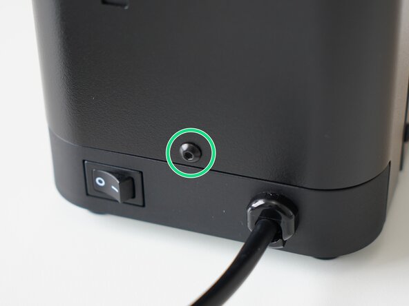
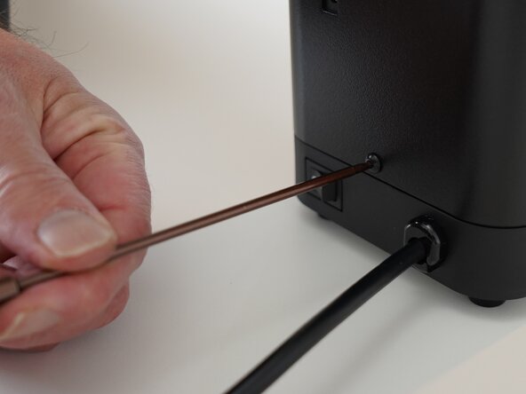
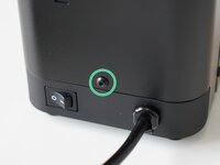
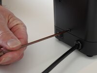
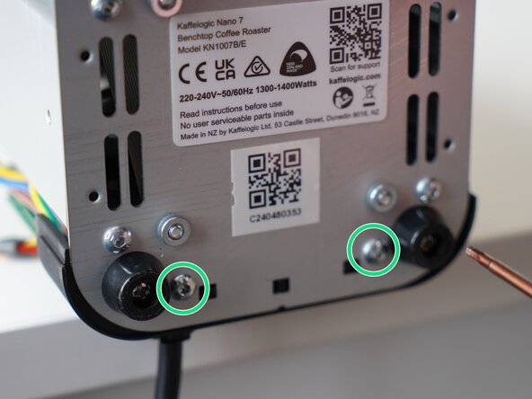
    • Remove the last 2.5mm Hex screw securing the rear panel.

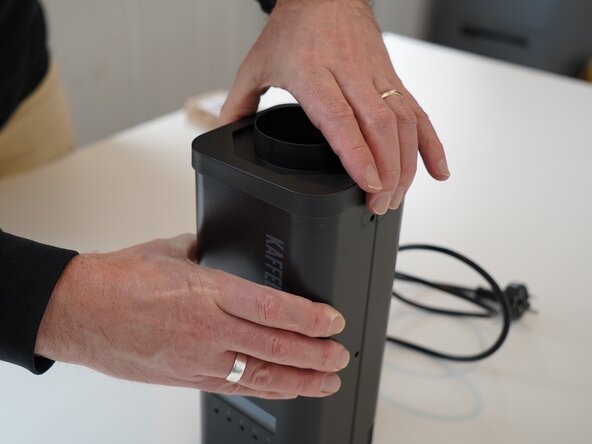
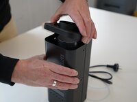
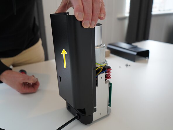
    • Pull up on the rear panel to remove it from the roaster.

  5. Kaffelogic Nano 7/LINK (D-P Serial) Mainboard Replacement, Access granted: step 5, image 1 of 2 Kaffelogic Nano 7/LINK (D-P Serial) Mainboard Replacement, Access granted: step 5, image 2 of 2
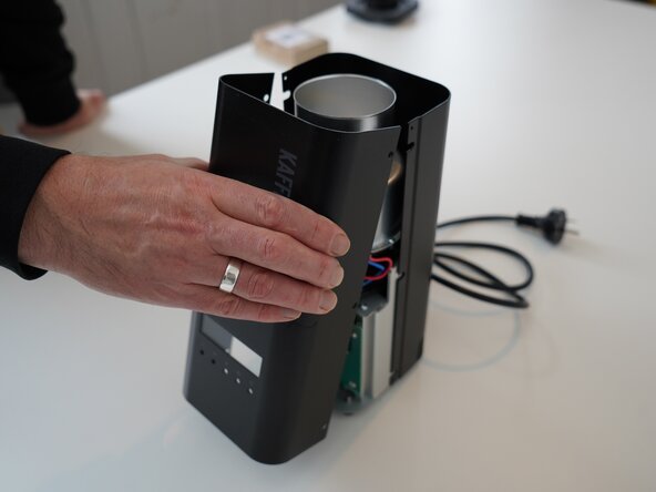
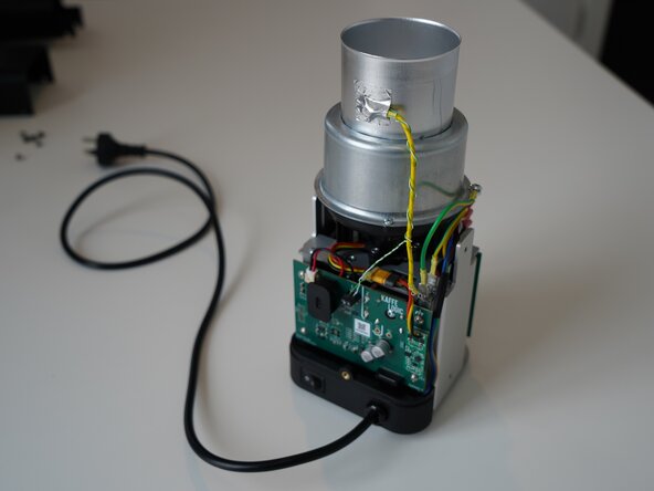
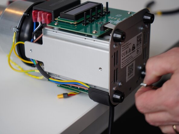
    • Set the panels aside somewhere safe and bask in the beauty of your naked roaster.

  6. Kaffelogic Nano 7/LINK (D-P Serial) Mainboard Replacement, Disconnect the thermocouple: step 6, image 1 of 3 Kaffelogic Nano 7/LINK (D-P Serial) Mainboard Replacement, Disconnect the thermocouple: step 6, image 2 of 3 Kaffelogic Nano 7/LINK (D-P Serial) Mainboard Replacement, Disconnect the thermocouple: step 6, image 3 of 3
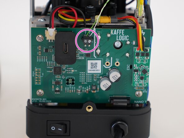
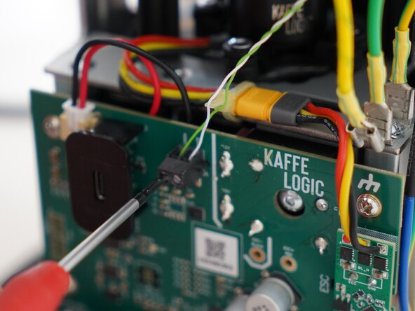
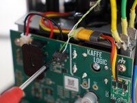
    • Use a 2.0mm slotted screwdriver to remove the thermocouple wires from the PCB-A

  7. Kaffelogic Nano 7/LINK (D-P Serial) Mainboard Replacement, Disconnect the motor: step 7, image 1 of 2 Kaffelogic Nano 7/LINK (D-P Serial) Mainboard Replacement, Disconnect the motor: step 7, image 2 of 2
    • Disconnect the motor cable, this may take some wiggling.

    • Refrain from using pliers or metal tools on this connector, as the plastic insulation can be damaged.

  8. Kaffelogic Nano 7/LINK (D-P Serial) Mainboard Replacement, Disconnect the SSR signal: step 8, image 1 of 2 Kaffelogic Nano 7/LINK (D-P Serial) Mainboard Replacement, Disconnect the SSR signal: step 8, image 2 of 2
    • Pull upwards on the SSR signal connector to remove it.

  9. Kaffelogic Nano 7/LINK (D-P Serial) Mainboard Replacement, Remove the cable carrier: step 9, image 1 of 3 Kaffelogic Nano 7/LINK (D-P Serial) Mainboard Replacement, Remove the cable carrier: step 9, image 2 of 3 Kaffelogic Nano 7/LINK (D-P Serial) Mainboard Replacement, Remove the cable carrier: step 9, image 3 of 3
    • Remove the 2x 2.5mm Hex screws securing the cable carrier to the base.

    • Be careful not to lay the roaster on its front as the buttons can be damaged or broken off.

  10. Kaffelogic Nano 7/LINK (D-P Serial) Mainboard Replacement, Remove the ribbon connector: step 10, image 1 of 2 Kaffelogic Nano 7/LINK (D-P Serial) Mainboard Replacement, Remove the ribbon connector: step 10, image 2 of 2
    • Gently remove the ribbon connector.

  11. Kaffelogic Nano 7/LINK (D-P Serial) Mainboard Replacement, Remove PCB screws: step 11, image 1 of 1
    • Unscrew the 4x PH2 PCB screws.

    • These screws are captive to the PCB.

  12. Kaffelogic Nano 7/LINK (D-P Serial) Mainboard Replacement, Remove the PCB: step 12, image 1 of 3 Kaffelogic Nano 7/LINK (D-P Serial) Mainboard Replacement, Remove the PCB: step 12, image 2 of 3 Kaffelogic Nano 7/LINK (D-P Serial) Mainboard Replacement, Remove the PCB: step 12, image 3 of 3
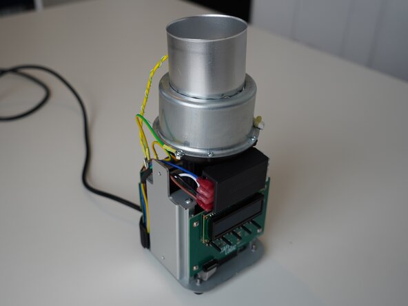
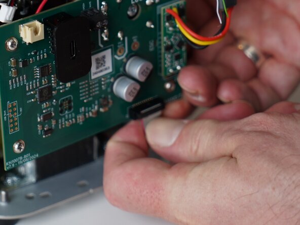
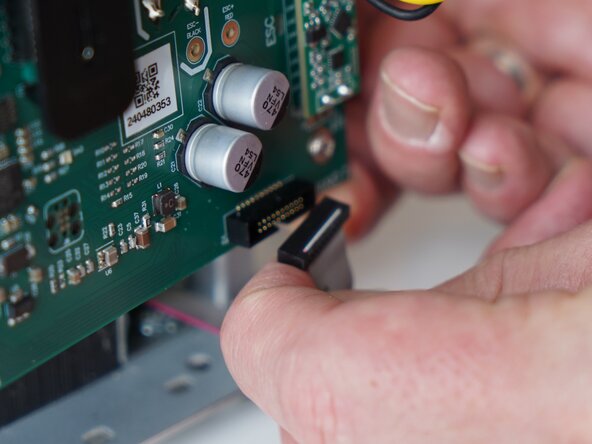
    • Pull the PCB away from the base assembly.

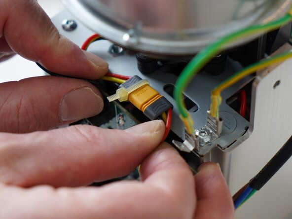
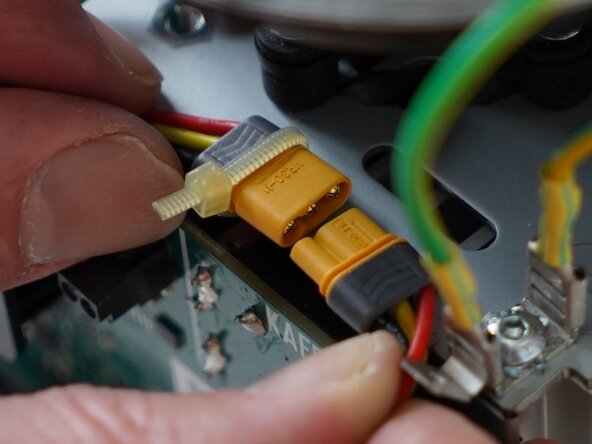
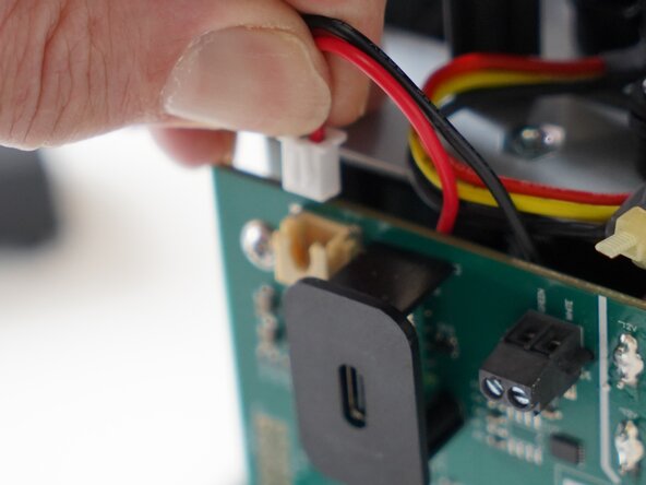
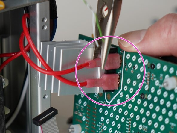
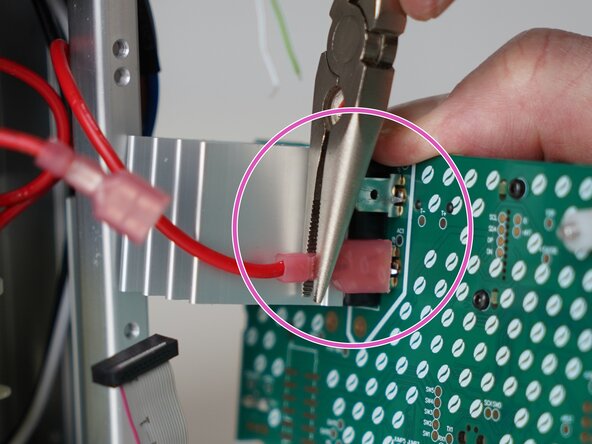
    • Use pliers to disconnect the transformer secondary wires from the back of the PCB

    • The transformer wires may be reconnected in either orientation. If you are replacing the USB daughterboard, you can choose to leave these wires in place.

  13. Kaffelogic Nano 7/LINK (D-P Serial) Mainboard Replacement, PCB Removed: step 13, image 1 of 3 Kaffelogic Nano 7/LINK (D-P Serial) Mainboard Replacement, PCB Removed: step 13, image 2 of 3 Kaffelogic Nano 7/LINK (D-P Serial) Mainboard Replacement, PCB Removed: step 13, image 3 of 3
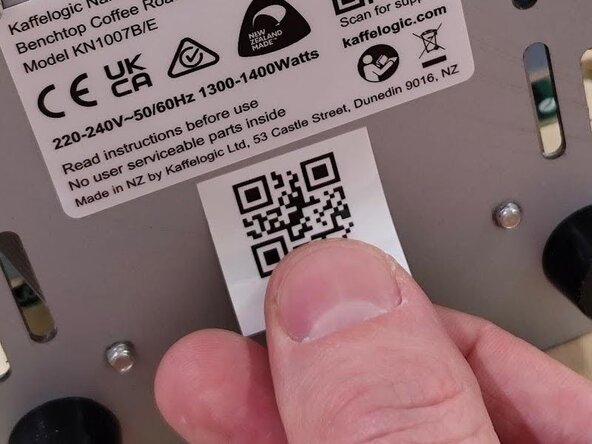
    • Your mainboard is now removed and ready for rework or replacement. Replace the serial code on the bottom of your roaster with the included QR label.

    • Head through to our wiki for instructions on recalibrating your fan speed and setting the voltage and element resistance after replacing the mainboard.

    • Nucleus Link anemometer calibration instructions can be found here.

Conclusion

To reassemble your device, follow these instructions in reverse order.

Kaffelogic

Member since: 07/23/25

2,098 Reputation

18 Guides authored

Team

Kaffelogic Staff Member of Kaffelogic Staff

Community

3 Members

18 Guides authored

0 Guide Comments

Add Comment

View Statistics:

Past 24 Hours: 1

Past 7 Days: 4

Past 30 Days: 15

All Time: 45