What you need
-
-
-
This is the JMGO GS1. It is the same machine as G1, but a little bit more improved in image quality... and with a more premium color: gold instead of silver. But internally, it is basically the same machine.
 Ask FixBot
-
-
-
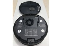
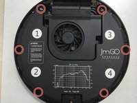
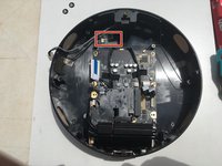
The first thing to do in order to disassemble the projector:
-
Three feet supporting the projector. You can unscrew them by hand.
-
One Phillips 1 screw.
-
Turn the bottom case a little bit to the left.
-
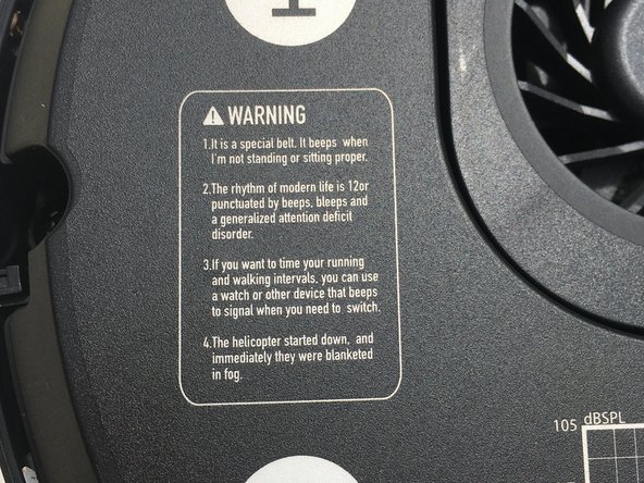
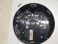
Now we can see the internals of the projector.
-
-
-
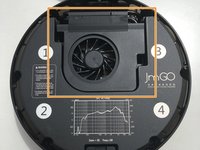
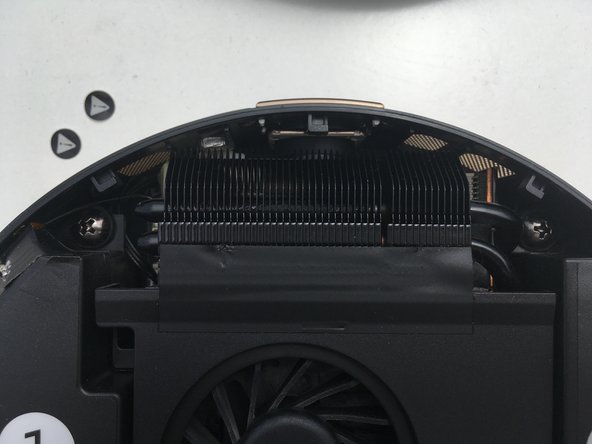
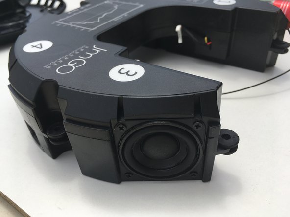
Here you can see the powerful speakers, and the fan that keeps the projector cool. And I think this view is also cool, don't you?
-
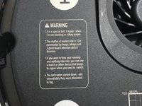
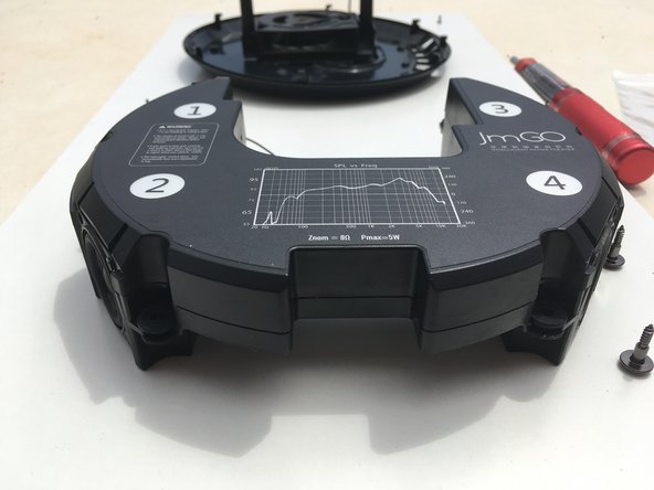
The first thing we can see is some information regarding the sound capabilities of the machine. Nice detail.
-
The numbers are just the location of each of the four speakers. Although what it seems the explanation of each of them is... weird. Mix of life advice, and strange facts...
-
-
-
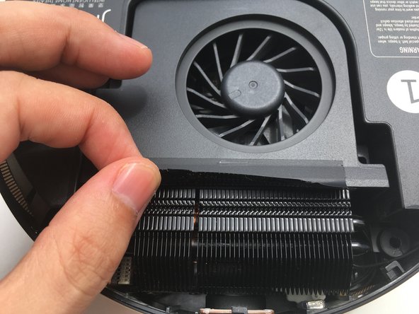
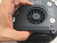
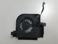
Now it's time for the fan.
-
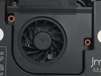
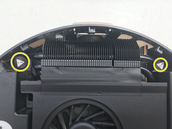
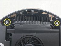
Peel off the sticker joining the fan to the heat sink, you don't need to remove it completely, just to split the two components.
-
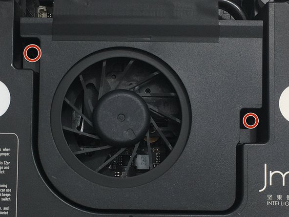
Remove the two screws located here.
-
-
-
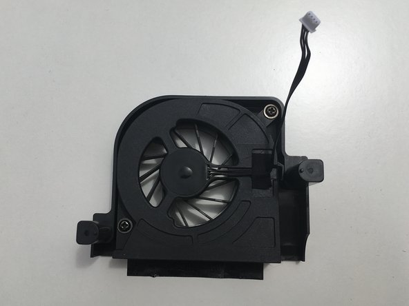
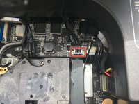
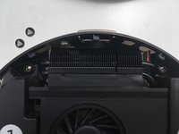
Carefully lift up the fan. Take care as it is still connected to the projector.
-
Pull up the connector to liberate the fan.
-
-
-
The Speakers have a total of 6 screws.
-
Two of them are covered by a warn signal. Don't worry, take off the sticks and, go ahead!
-
You see? no dragons down there.
-
-
-
Lift slightly up the speakers to have access to the connectors to the matherboard.
-
Pull out the connectors and free the speakers.
-
Disconnect the antena from the WiFi/Bluetooth card and free the speakers.
-
-
-
-
Here you can see the antenna attached to the speakers.
-
And a little more detail on the speaker component itself.
-
-
-
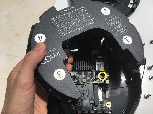
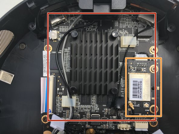
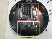
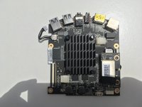
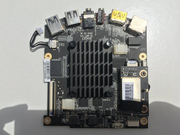
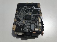
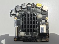
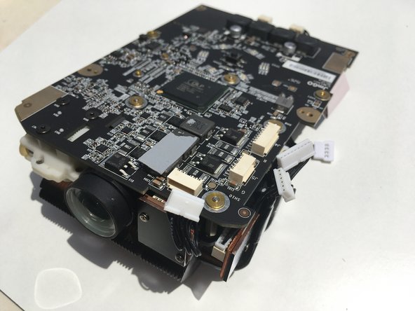
Here we can see what is left from the device.
-
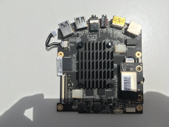
The main board, which hosts the Android OS.
-
This is the WiFi module.
-
And the optics part of the projector. Underneath the main board there is the other part for the projector to work: the DLP electronics.
-
Time to continue disassembling it.
-
-
-
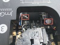
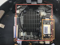
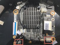
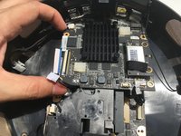
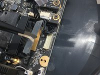
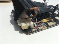
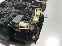
We start disconnecting power cable, and the connection with the DPL board.
-
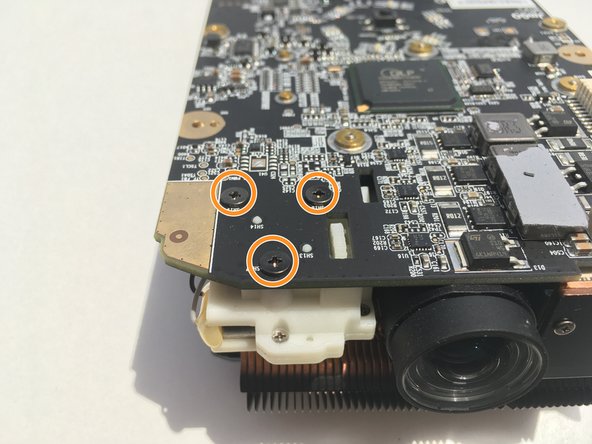
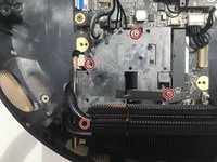
Then unscrew the three left screws securing the board to the main body.
-
-
-
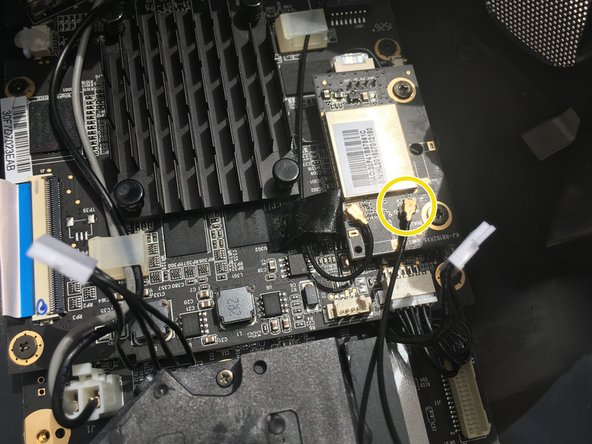
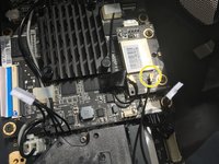
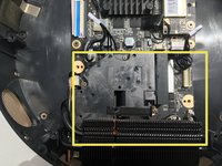
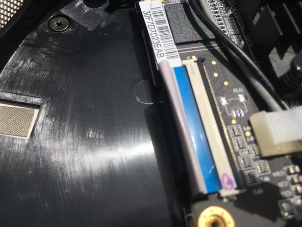
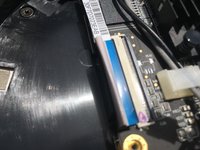
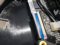
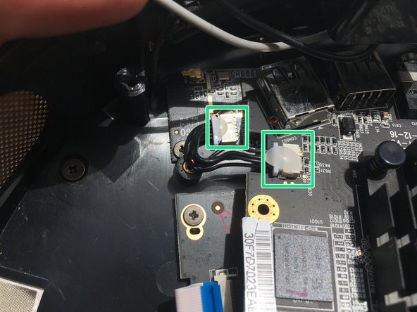
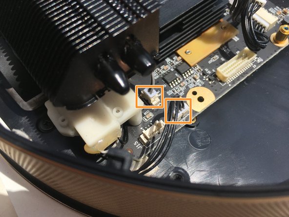
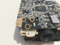
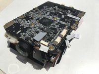
Move the board a little bit to the side to expose the last connection.
-
The both connectors at the end of the cable are held in place by glue. Chose the one easier for you to disconnect.
-
-
-
Now we will disassembly the DLP board.
-
I think this board is the bluetooth, but not sure.
-
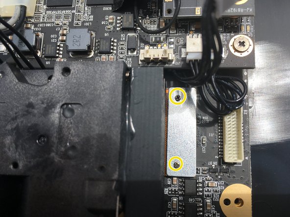
First, we unscrew the plate securing the connection of the board with the optics.
-
-
-
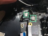
We disconnect the antenna.
-
This two screws.
-
And some more connections.
-
And the whole board can know be extracted.
-
-
-
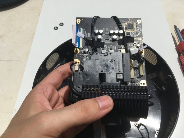
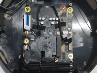
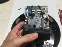
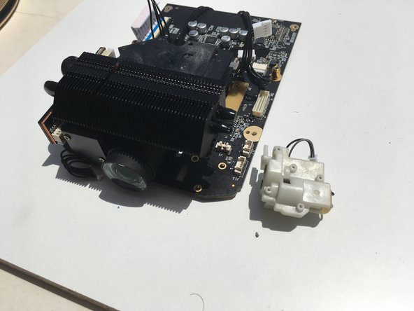
Let's have a break and admire the three big pieces that compose this JmGO GS1 device.
-
-
-
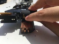
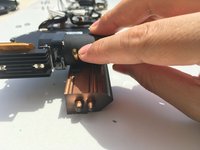
Disconnect the motor from the board.
-
Undo this three screws.
-
And the motor is free now to be extracted.
-
-
-
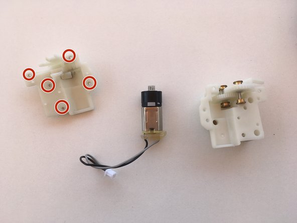
There are four screws to undo.
-
And these three connections.
-
-
-
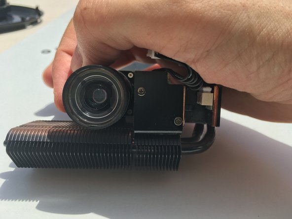
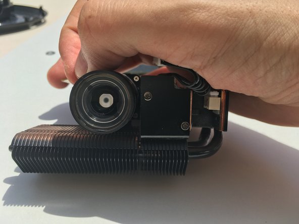
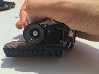
The motor uses a small lever to move the focus.
-
This is how it looks in the lower position.
-
-
-
You can disassembly the motor and give it a good lubrication (I had to do it, that is main the reason of this guide).
-
Sorry for not showing you the screws, I forgot to photograph them, but they are located here. Five in total.
-
-


To reassemble your device, follow these instructions in reverse order.

14 Guide Comments
What voltage is the motor, I stripped it down and put it all back together but focus still not working everything else works :(
I also had problems with focus, it was a trial of prove and error, but I ended opening the motor because maybe it was a problem of some contacts. if you feel like you have the ability to check that and put it back together then give it a try. Anyway after I put back everything together, I hear the motor was working but the focus wasn't working and I realized it was because the casing that puts the motors and the gears together was too tight, so I loosed the screws a little bit and it was working great again :). I hope it helps
Good news,
I checked the connector voltages for the focus motor and it was giving out -1.7v to +1.7v depending on direction of focus in or out. I then tested the continuity of the tiny focus motor expecting 10 Ohms or thereabouts (the motor winding through the commutator). Open circuit!!
I dismantled the focus unit, all the cogs were fine and the tiny keyway into the motor drive cog was intact.
I prized open the motor tabs and removed the armature. gave the commutator a clean. Tested the continuity between the 3 commutators and 10 ohms between each so armature is good. Rebuilt motor and checked again 10ohms thos time. Tested the motor using 1.5v battery and it and the gearbox now work fine.
Rebuilt projector and now have focus again :) happy days.
Wow, you have knowledge man.
Yes, when I opened the projector I tested the motor with a normal AA battery to check that it was moving. In my case it was easier than in you case. I cleaned the motor housing and, after putting back all together, it worked just fine.
Tengo un problema con el jmgo G1pro. Al ponerle la alimentación se enciende directamente el los led del botón de encendido se ponen casi verde, la pantalla se pone solo azul y no hace mas nada. Piede tener solución?