Free Shipping on Domestic Orders $75+

Internal Assembly Removal

Prerequisite Only
This is a prerequisite-only guide! This guide is part of another procedure and isn’t meant to be used alone.

What you need

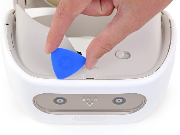
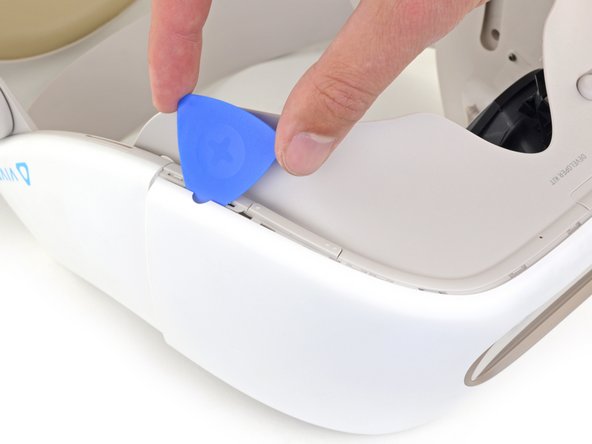
    1. Internal Assembly Removal, Remove the facerest cushion: step 1, image 1 of 3 Internal Assembly Removal, Remove the facerest cushion: step 1, image 2 of 3 Internal Assembly Removal, Remove the facerest cushion: step 1, image 3 of 3
      • Place your device upside-down on your work surface.

      • The facerest cushion is lightly held into place by seven plastic clips.

      • Use your fingers to gently pull the facerest cushion straight off of the facerest to remove it.

      Ask FixBot

      Add Comment

    1. Internal Assembly Removal, Remove the facerest: step 2, image 1 of 1
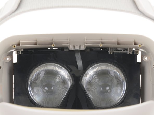
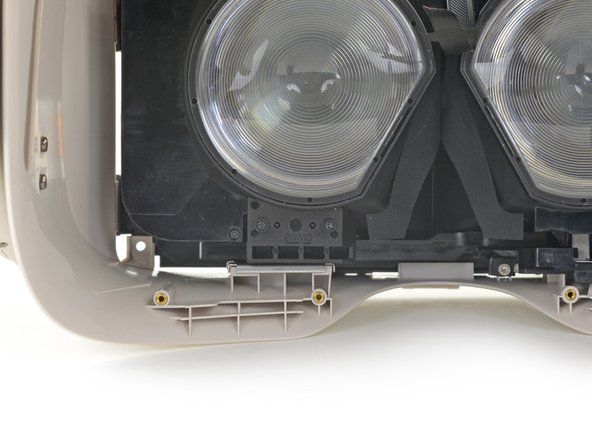
      • Use a T5 Torx screwdriver to remove the eight 4.5 mm screws securing the facerest.

      • One of the screws will be covered by a tamper-evident sticker. Press the driver through the sticker to remove the screw.

      Ask FixBot

      Add Comment

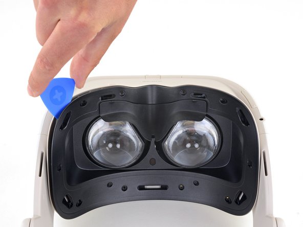
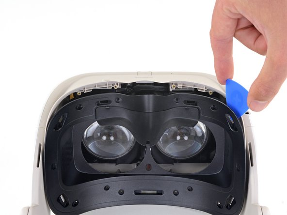
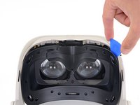
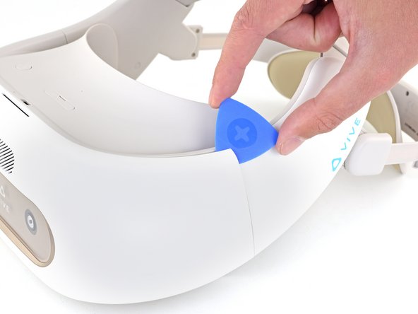
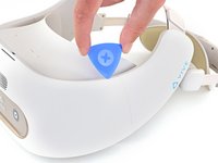
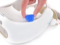
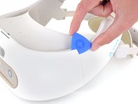
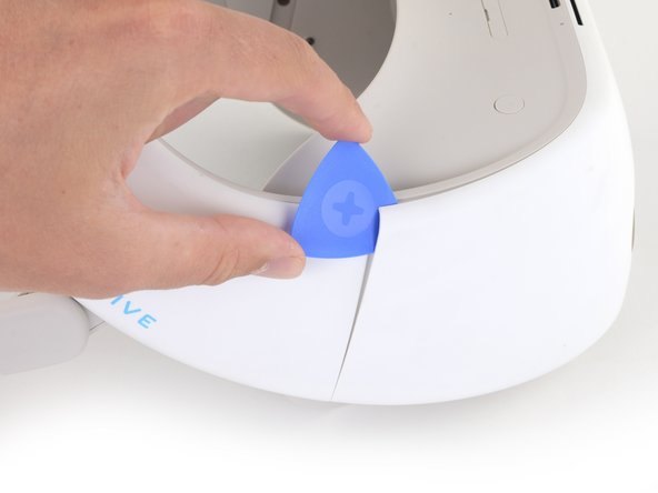
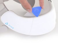
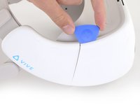
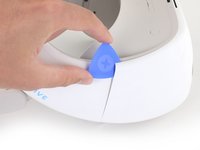
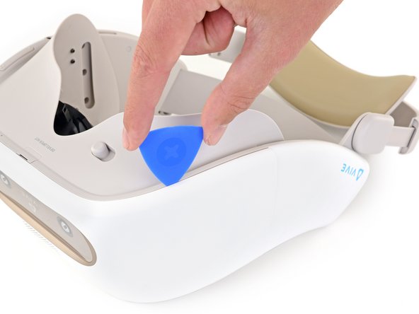
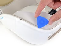
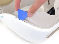
    2. Internal Assembly Removal: step 3, image 1 of 3 Internal Assembly Removal: step 3, image 2 of 3 Internal Assembly Removal: step 3, image 3 of 3
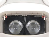
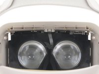
      • Insert an opening pick into the upper-left corner of the facerest.

      • Twist the opening pick to release the plastic clip securing the facerest.

      • Repeat for the upper-right corner.

      • Don't remove the facerest yet. It's still attached by the facerest sensor ribbon cable.

      Ask FixBot

      Add Comment

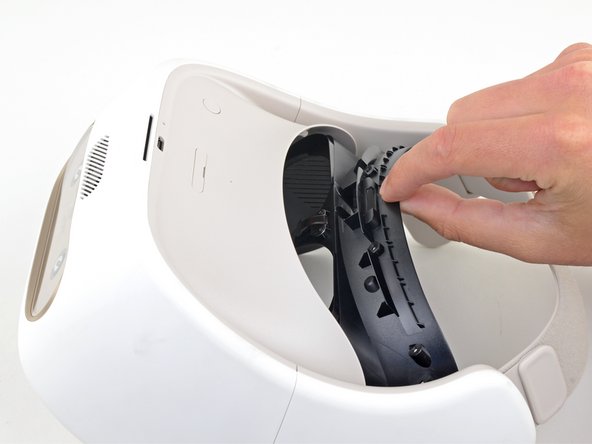
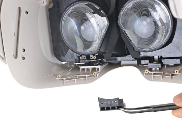
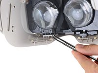
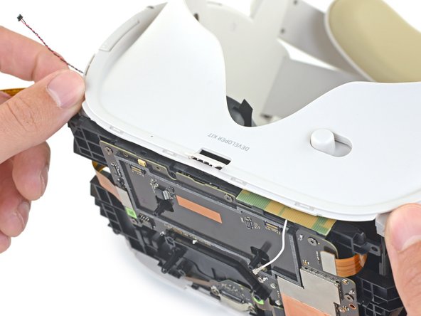
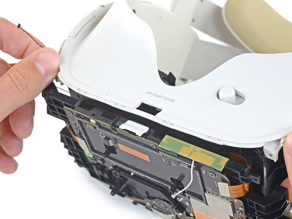
    3. Internal Assembly Removal, Remove the facerest sensor: step 4, image 1 of 3 Internal Assembly Removal, Remove the facerest sensor: step 4, image 2 of 3 Internal Assembly Removal, Remove the facerest sensor: step 4, image 3 of 3
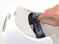
      • Carefully flip your device over.

      • Pull the facerest out just enough to access the screws securing the facerest sensor.

      • Don't put any strain on the facerest sensor ribbon cable.

      • During reassembly, make sure the facerest sensor ribbon cable is positioned between the lenses before reinstalling the facerest.

      Ask FixBot

      Add Comment

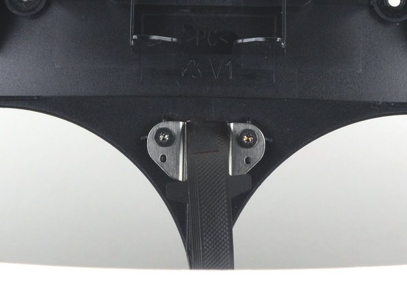
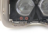
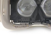
    4. Internal Assembly Removal: step 5, image 1 of 1
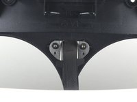
      • Use a T5 Torx screwdriver to remove the two 2.4 mm screws securing the facerest sensor to the facerest.

      Ask FixBot

      Add Comment

    5. Internal Assembly Removal: step 6, image 1 of 1
      • Remove the facerest.

      Ask FixBot

      Add Comment

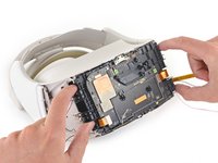
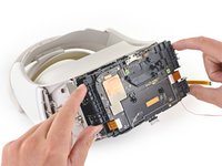
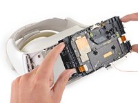
    1. Internal Assembly Removal, Unscrew the front cover: step 7, image 1 of 2 Internal Assembly Removal, Unscrew the front cover: step 7, image 2 of 2
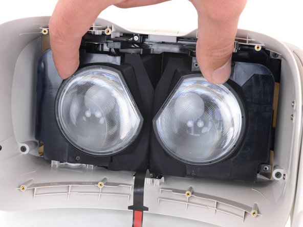
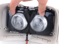
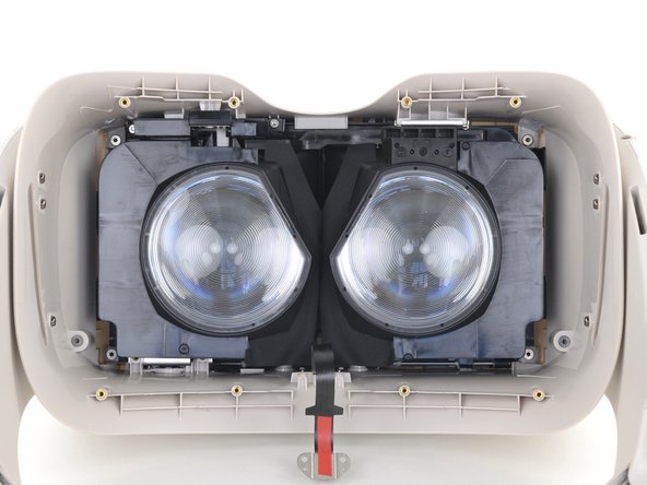
      • Use your fingers to slide the lenses towards each other so that they are positioned towards the center of the device.

      Ask FixBot

      Add Comment

    2. Internal Assembly Removal: step 8, image 1 of 2 Internal Assembly Removal: step 8, image 2 of 2
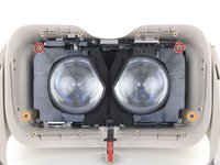
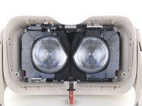
      • Use a T5 Torx screwdriver to remove the four screws securing the front cover from inside the device:

      • Two 5.7 mm screws with fine threads

      • Two 5.5 mm screws with coarse threads

      • The coarse-thread screws can strip easily. During reassembly, tighten the coarse-thread screws until they're hand tight and then no more.

      Ask FixBot

      Add Comment

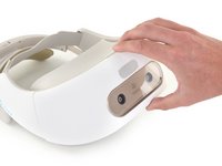
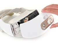
    3. Internal Assembly Removal, Remove the front cover: step 9, image 1 of 2 Internal Assembly Removal, Remove the front cover: step 9, image 2 of 2
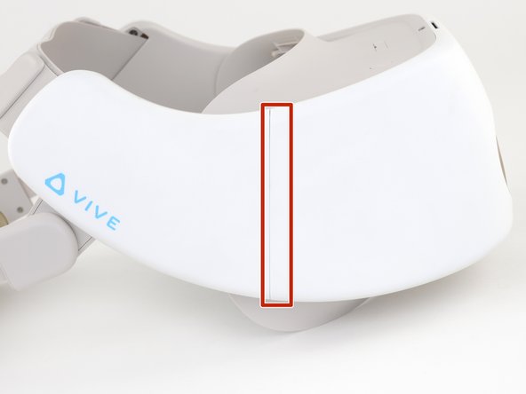
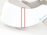
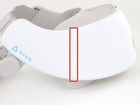
      • Note the location of the plastic welds on both vertical edges of the front cover.

      • After reassembly, the gap between the front cover and the side panels may no longer be flush. This is a cosmetic defect only and will not affect operation. The front cover's clips and screws are sufficient to secure it to the rest of the device.

      Ask FixBot

      Add Comment

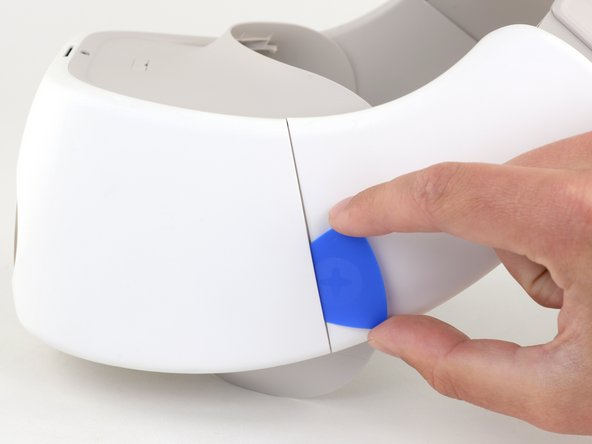
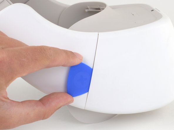
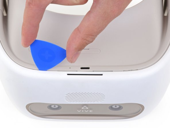
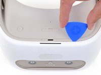
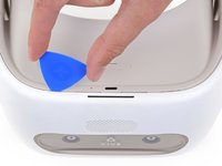
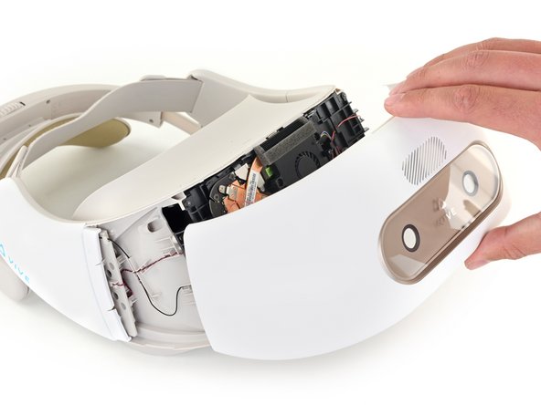
    4. Internal Assembly Removal: step 10, image 1 of 3 Internal Assembly Removal: step 10, image 2 of 3 Internal Assembly Removal: step 10, image 3 of 3
      • Insert an opening pick into the top of the front cover near the upper left corner.

      • Slide the opening pick around the upper left corner of the front cover.

      Ask FixBot

      Add Comment

    5. Internal Assembly Removal: step 11, image 1 of 2 Internal Assembly Removal: step 11, image 2 of 2
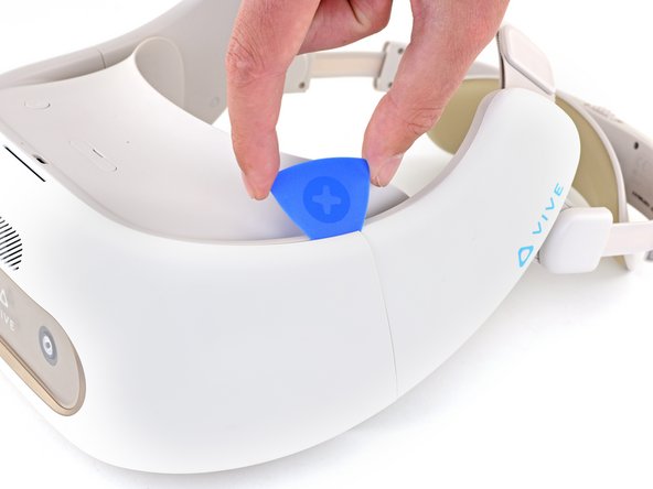
      • Use the opening pick to separate the weld securing the left side vertical edge of the front cover.

      • The weld may require significant force to separate.

      Ask FixBot

      Add Comment

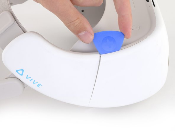
    6. Internal Assembly Removal: step 12, image 1 of 3 Internal Assembly Removal: step 12, image 2 of 3 Internal Assembly Removal: step 12, image 3 of 3
      • Insert an opening pick into the top of the front cover near the upper right corner.

      • Slide the opening pick around the upper right corner of the front cover.

      Ask FixBot

      Add Comment

    7. Internal Assembly Removal: step 13, image 1 of 2 Internal Assembly Removal: step 13, image 2 of 2
      • Use the opening pick to separate the weld securing the right side vertical edge of the front cover.

      • The weld may require significant force to separate.

      Ask FixBot

      Add Comment

    8. Internal Assembly Removal: step 14, image 1 of 3 Internal Assembly Removal: step 14, image 2 of 3 Internal Assembly Removal: step 14, image 3 of 3
      • Flip the device upside-down.

      • Use an opening pick to disconnect the plastic clips securing the bottom right edge of the front cover to the device.

      Ask FixBot

      Add Comment

    9. Internal Assembly Removal: step 15, image 1 of 2 Internal Assembly Removal: step 15, image 2 of 2
      • Slide the opening pick along the bottom edge of the front cover to separate it from the device.

      Ask FixBot

      Add Comment

    10. Internal Assembly Removal: step 16, image 1 of 2 Internal Assembly Removal: step 16, image 2 of 2
      • Use the opening pick to disconnect the plastic clips securing the bottom-left edge of the front cover to the device.

      Ask FixBot

      Add Comment

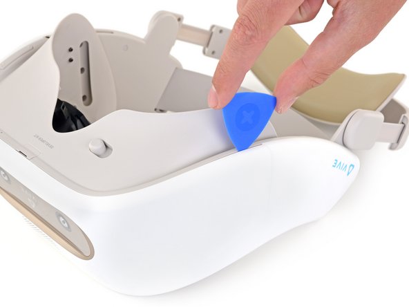
    11. Internal Assembly Removal: step 17, image 1 of 2 Internal Assembly Removal: step 17, image 2 of 2
      • Flip the device right-side up.

      • Use the opening pick to separate the last few plastic clips securing the top of the front cover.

      Ask FixBot

      Add Comment

    12. Internal Assembly Removal: step 18, image 1 of 2 Internal Assembly Removal: step 18, image 2 of 2
      • Remove the front cover.

      Ask FixBot

      Add Comment

    1. Internal Assembly Removal, Remove the CPU fan: step 19, image 1 of 3 Internal Assembly Removal, Remove the CPU fan: step 19, image 2 of 3 Internal Assembly Removal, Remove the CPU fan: step 19, image 3 of 3
      Tool used on this step:
      Tweezers
      $3.99
      Buy
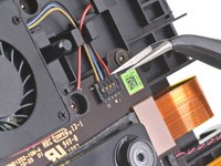
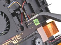
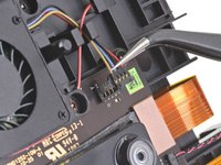
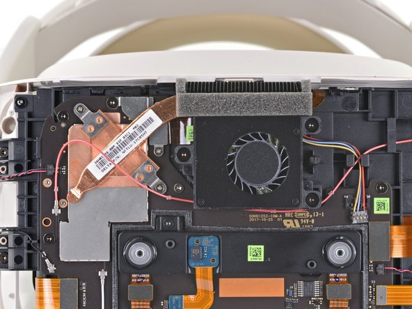
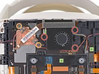
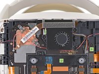
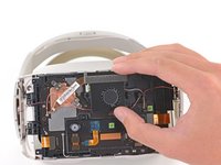
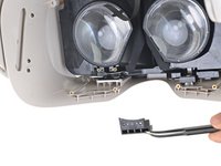
      • Use a pair of angled tweezers to disconnect the CPU fan cable from the motherboard.

      • Lift the CPU fan connector straight up from the motherboard to disconnect it from its socket.

      • During reassembly, align the CPU fan connector with its socket and use your finger to press it straight down into the motherboard.

      Ask FixBot

      Add Comment

    2. Internal Assembly Removal: step 20, image 1 of 2 Internal Assembly Removal: step 20, image 2 of 2
      • Use a T5 Torx screwdriver to remove the three 5.5 mm screws securing the CPU fan.

      • Use a Phillips screwdriver to remove the two 2.3 mm screws securing the CPU heatsink.

      Ask FixBot

      Add Comment

    3. Internal Assembly Removal: step 21, image 1 of 2 Internal Assembly Removal: step 21, image 2 of 2
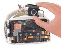
      • Remove the CPU fan.

      • During reassembly, do not sandwich the red antenna cable between the heatsink and contact plates.

      Ask FixBot

      Add Comment

    1. Internal Assembly Removal, Disconnect the power button: step 22, image 1 of 2 Internal Assembly Removal, Disconnect the power button: step 22, image 2 of 2
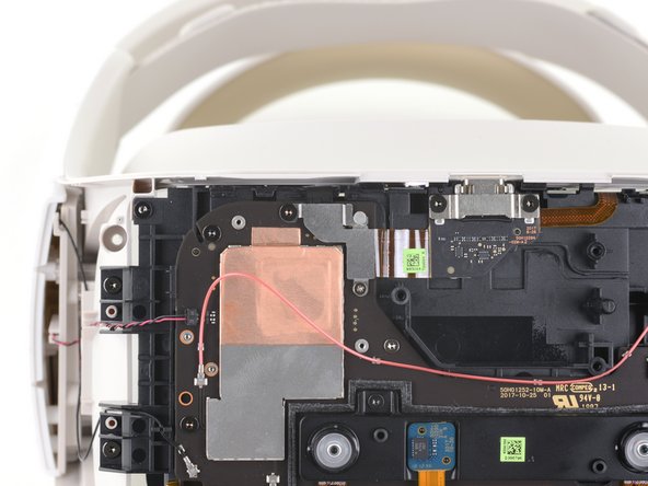
      • Use a T5 Torx screwdriver to remove the black 5.5 mm screw from the power button cable bracket.

      • Use a Phillips screwdriver to remove the 2.3 mm screw from the power button cable bracket.

      Ask FixBot

      Add Comment

    2. Internal Assembly Removal: step 23, image 1 of 2 Internal Assembly Removal: step 23, image 2 of 2
      Tool used on this step:
      Tweezers
      $4.99
      Buy
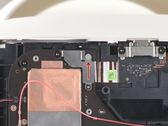
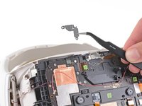
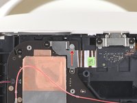
      • Use a pair of tweezers or your fingers to remove the power button cable bracket from the motherboard.

      • During reassembly, slot the power button cable bracket back onto the peg on the motherboard before reinstalling the screws.

      Ask FixBot

      Add Comment

    3. Internal Assembly Removal: step 24, image 1 of 2 Internal Assembly Removal: step 24, image 2 of 2
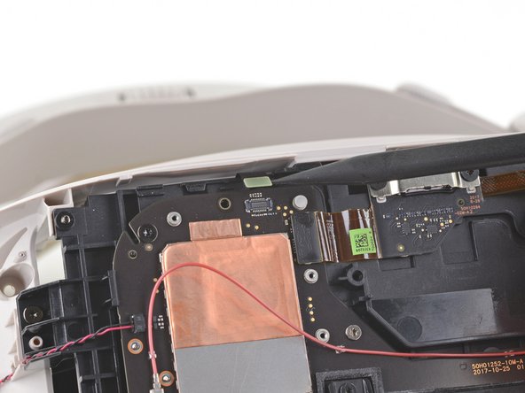
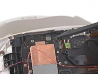
      • Use the pointed end of a spudger to disconnect the power button cable from the motherboard.

      Ask FixBot

      Add Comment

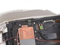
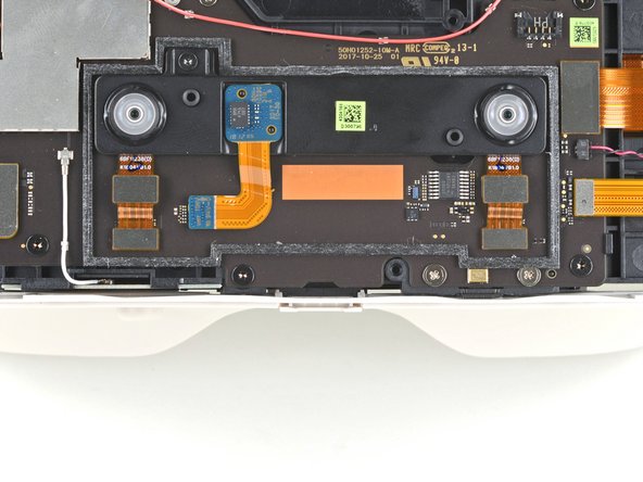
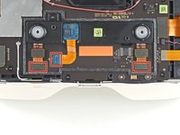
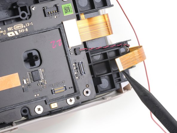
    4. Internal Assembly Removal, Remove the proximity sensor array: step 25, image 1 of 2 Internal Assembly Removal, Remove the proximity sensor array: step 25, image 2 of 2
      • Pry up with the flat end of a spudger to disconnect the three ribbon cables connecting the proximity sensor array to the motherboard.

      Ask FixBot

      Add Comment

    5. Internal Assembly Removal: step 26, image 1 of 2 Internal Assembly Removal: step 26, image 2 of 2
      • Use a T5 Torx screwdriver to remove the 4.5 mm screw from the proximity sensor array.

      Ask FixBot

      Add Comment

    6. Internal Assembly Removal: step 27, image 1 of 1
      • Remove the proximity sensor array from the motherboard.

      Ask FixBot

      Add Comment

    7. Internal Assembly Removal, Remove the internal assembly: step 28, image 1 of 3 Internal Assembly Removal, Remove the internal assembly: step 28, image 2 of 3 Internal Assembly Removal, Remove the internal assembly: step 28, image 3 of 3
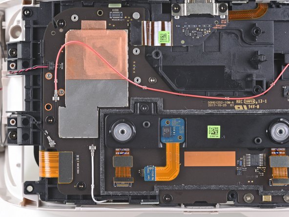
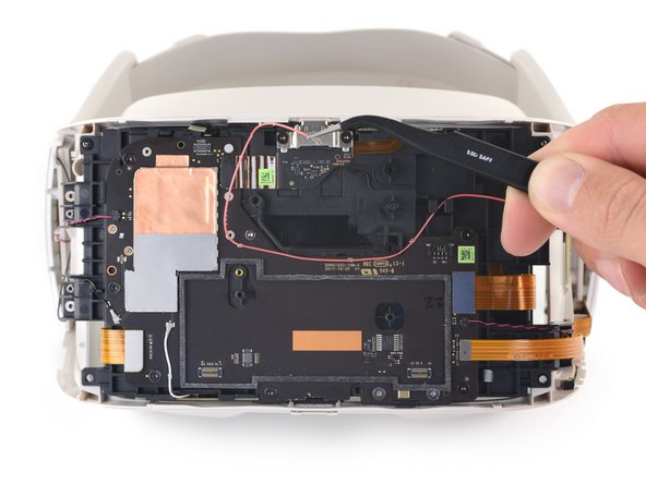
      • Antenna connectors are fragile and can break off of the motherboard. Use this technique when disconnecting antenna cables.

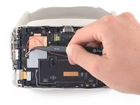
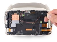
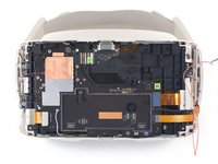
      • Use a spudger or a pair of tweezers to disconnect the red antenna cable from the front of the device.

      • De-route the antenna cable from the front of the device and place it to the side.

      • During reassembly, be sure to re-route the cable through the brackets and clips securing it.

      Ask FixBot

      Add Comment

    8. Internal Assembly Removal: step 29, image 1 of 3 Internal Assembly Removal: step 29, image 2 of 3 Internal Assembly Removal: step 29, image 3 of 3
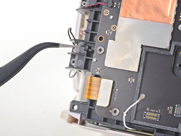
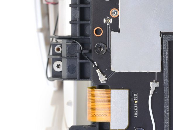
      • Use a spudger or a pair of tweezers to remove the black antenna cable from the motherboard.

      • During reassembly, re-route the black antenna cable through its channel and clip.

      Ask FixBot

      Add Comment

    9. Internal Assembly Removal: step 30, image 1 of 2 Internal Assembly Removal: step 30, image 2 of 2
      • Use a spudger to disconnect the ribbon cable connecting the volume buttons and headset jack to the motherboard.

      Ask FixBot

      Add Comment

    10. Internal Assembly Removal: step 31, image 1 of 2 Internal Assembly Removal: step 31, image 2 of 2
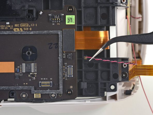
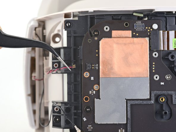
      • Use a pair of tweezers to carefully disconnect the speaker wire from the right side of the motherboard.

      • During reassembly, reinstall the speaker wire with the gold contacts facing towards you and the red wire on top.

      Ask FixBot

      Add Comment

    11. Internal Assembly Removal: step 32, image 1 of 2 Internal Assembly Removal: step 32, image 2 of 2
      • Use a pair of tweezers to carefully disconnect the speaker wire from the left side of the motherboard.

      • During reassembly, reinstall the speaker wire with the gold contacts facing towards you and the black wire on top.

      Ask FixBot

      Add Comment

    12. Internal Assembly Removal: step 33, image 1 of 2 Internal Assembly Removal: step 33, image 2 of 2
      • Use a T5 Torx screwdriver to remove the four 5.6 mm screws securing the corners of the internal assembly to the frame.

      • Use a Phillips screwdriver to remove the two 7.2 mm silver screws from the bottom of the motherboard.

      Ask FixBot

      Add Comment

    13. Internal Assembly Removal: step 34, image 1 of 2 Internal Assembly Removal: step 34, image 2 of 2
      • Use a T5 Torx screwdriver to remove the two 5.5 mm screws securing the internal assembly to inside of the frame.

      • During reassembly, make sure the internal assembly is fully seated on its centering pegs on each side and sits flush on the tabs on the frame before tightening these two screws.

      • Check for proper rack and pinion operation before continuing reassembly.

      Ask FixBot

      Add Comment

    14. Internal Assembly Removal: step 35, image 1 of 2 Internal Assembly Removal: step 35, image 2 of 2
      • Use a T5 Torx screwdriver to remove the two 4.5 mm screws securing the bracket under the left lens.

      Ask FixBot

      Add Comment

    15. Internal Assembly Removal: step 36, image 1 of 2 Internal Assembly Removal: step 36, image 2 of 2
      • Remove the bracket under the left lens.

      • To ensure correct operation, make sure this piece is properly seated on the adjuster mechanism by sliding the lenses as close together as possible before reinstalling it.

      Ask FixBot

      Add Comment

    16. Internal Assembly Removal: step 37, image 1 of 3 Internal Assembly Removal: step 37, image 2 of 3 Internal Assembly Removal: step 37, image 3 of 3
      • Before removing the internal assembly, tilt the front out slightly to feed the microSD card slot cover through the frame.

      Ask FixBot

      Add Comment

    17. Internal Assembly Removal: step 38, image 1 of 3 Internal Assembly Removal: step 38, image 2 of 3 Internal Assembly Removal: step 38, image 3 of 3
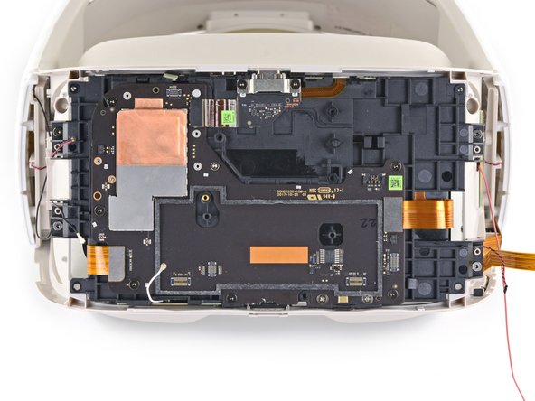
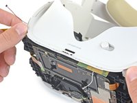
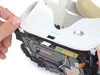
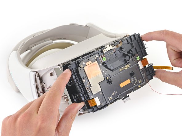
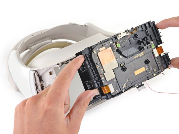
      • Carefully remove the internal assembly through the front of the device.

      • The internal assembly may not come out easily. Gently bend the outer frame as necessary to create space for the edges to clear.

      • Do not force any part of the internal assembly out.

      • During reassembly, feed the microSD slot cover referenced in the previous step back through the frame as you slide the internal assembly back into place.

      Ask FixBot

      Add Comment

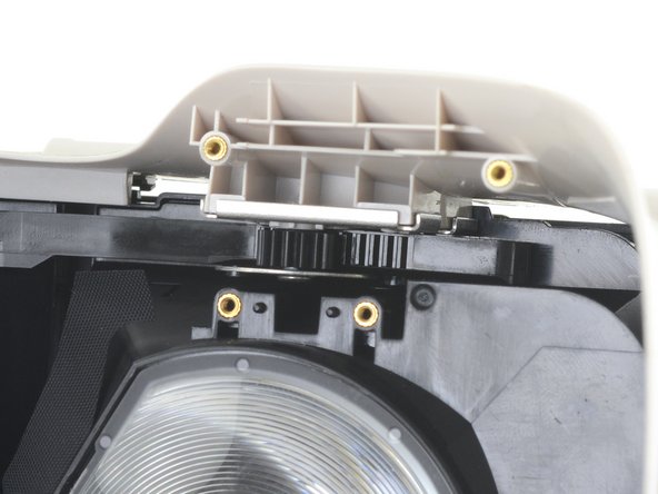
    18. Internal Assembly Removal, Reassembly tips: step 39, image 1 of 2 Internal Assembly Removal, Reassembly tips: step 39, image 2 of 2
      • During reassembly:

      • Make sure not to trap any of the five loose wires and cables when reinstalling the internal assembly.

      • Hold the lenses as close together as possible and align the rack and pinion with the gear and washer.

      • This will ensure the lenses are properly aligned.

      Ask FixBot

      Add Comment

Conclusion

To reassemble your device, follow the above steps in reverse order.

Repair didn’t go as planned? Try some basic troubleshooting, or ask our Answers community for help.

Cancel: I did not complete this guide.

Sam Omiotek

Member since: 02/25/19

100,791 Reputation

289 Guides authored

0 Guide Comments

Add Comment

View Statistics:

Past 24 Hours: 2

Past 7 Days: 3

Past 30 Days: 12

All Time: 292