Introduction
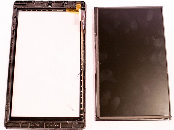
Broken screen is time to replace. For this replacement you will need to work from the back to the front of the tablet, the replacement of the screen will require the removal of the motherboard, since the screen is attached to the motherboard.
What you need
-
-
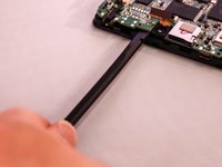
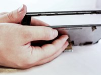
Insert the edge of the plastic opener into the grove between the screen and back cover around the perimeter of the device.
-
Then using a gentle prying motion, create a gap large enough to use your fingers to separate the two halves.
 Ask FixBot
-
-
-
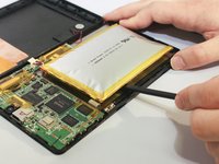
Place the tip of the spudger on each side of the battery's electrical connector.
-
Then using a gentle match-striking motion, loosen both sides of the battery's electrical connector.
-
-
-
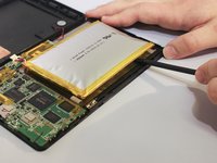
Insert the flat end of the spudger under one side of the battery.
-
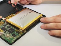
Then using a gentle prying and sliding motion, separate the battery from the case. There are two lengthwise strips of glue holding it down.
-
Repeat the process for the other side of the battery.
-
-
-
-
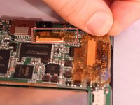
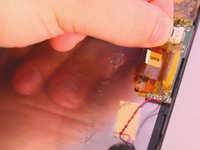
Locate the three ribbon cables connecting components to the motherboard. The connections are covered with orange shielding tape. Peel the tape off the connectors and reserve for reassembly.
-
-
-
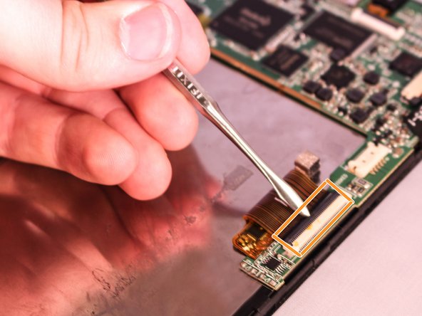
Each Zero Insertion Force or ZIF connector has a latch which holds the ribbon cable in place. The camera cable (a) and the LCD display cable (b) have a latch that lifts as shown in the illustration. Use a spudger to gently lift the latch to release the cable.
-
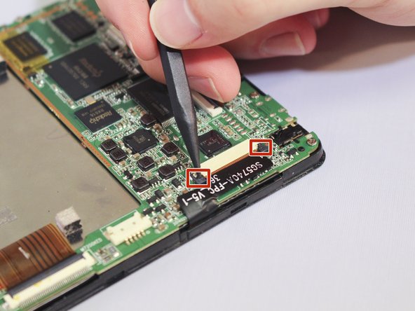
The touchscreen cable (c) has a sliding latch on each side of the connector. Use a spudger to carefully slide the latch on each side as shown to release the cable.
-
-
-
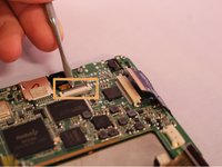
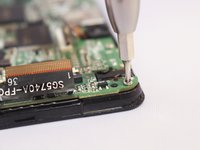
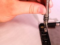
Using a Phillips #000 screwdriver, remove the six 4.8mm screws holding the motherboard to the case.
-
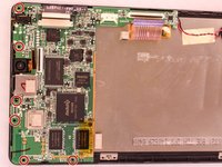
Using the spudger lift the motherboard from the case.
-
-
-
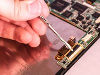
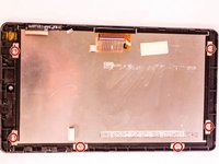
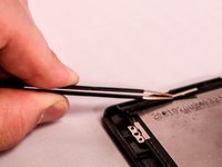
After you have removed the motherboard, use a Phillips #000 screwdriver to unscrew the six 2.9mm screws holding the LCD display to the screen. Using the twizzers remove the clips from the screen.
-


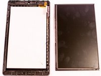
To reassemble your device, follow these instructions in reverse order.
Cancel: I did not complete this guide.
3 other people completed this guide.
Team

Eastern Washington University, Team 1-6, Matresse Fall 2015 Member of Eastern Washington University, Team 1-6, Matresse Fall 2015
EWU-MATRESSE-F15S1G6
4 Members
10 Guides authored