Introduction
In order to access the core components of the Acer Aspire One 725-0845, you will need to remove the inner frame, detailed here.
What you need
-
-
-
Ensure the device is powered off by holding down the power button on the top left-hand side.
-
On a flat, level surface, flip the device over so that the back-plate is accessible.
 Ask FixBot
-
-
-
Using a spudger or any fine-pointed tool, push the release slide away from the center of the device.
-
Simultaneously pull the battery out and away from the device.
-
-
-
-
-
Using the JIS J1 Screwdriver Bit and Driver, remove the center screw (7.0 mm) from the back-plate.
-
Using your hands, slide the back-plate away from the center of the device and remove.
-
-
-
-
-
-
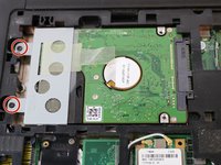
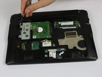
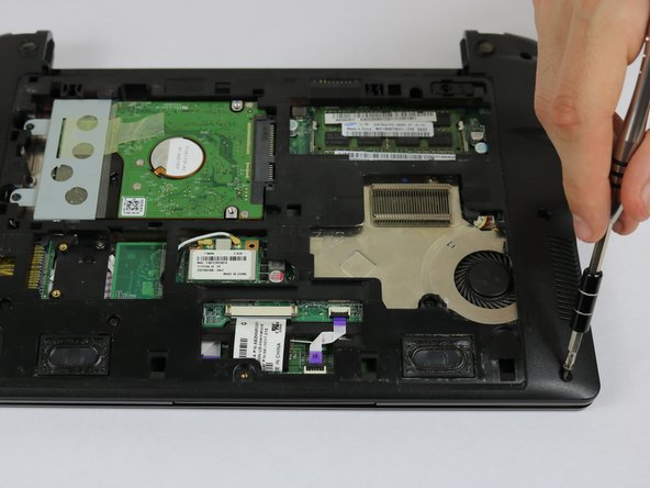
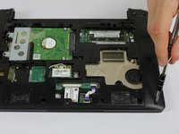
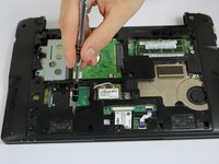
Using the JIS J1 Screwdriver Bit and Driver, remove the two screws (9.0 mm) from the outward side of the hard drive.
-
-
-
Using your hand, slide the hard drive away from the center of the device until it disconnects from the motherboard.
-
Carefully lift the outward side of the hard drive and place the drive on a clean, non-magnetic surface.
-
-
-
-
-
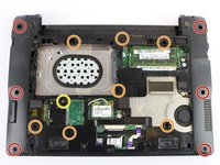
Using the JIS J1 Screwdriver Bit and Driver, remove the six outside screws (7.0 mm).
-
Using the JIS J1 Screwdriver Bit and Driver, remove the seven inside screws (8.0 mm).
-
Using the JIS J1 Screwdriver Bit and Driver, remove the one inside screw (3.0 mm).
-
-
-
Using your hands, slide the brown release tabs for the keyboard connection away from the center of the device.
-
Gently remove the keyboard connection by pulling away from the center of the device.
-
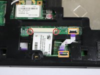
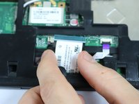
Lift the black locks for the touchpad connections into the upward position.
-
Gently remove the touchpad connections by pulling the purple tabs away from the locks.
-
-
-
Flip the device over and open it.
-
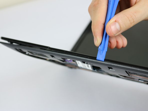
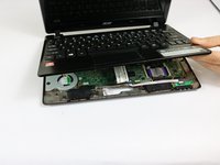
Using the plastic opening tools, remove the cover/palm rest from the frame of the device.
-
-









To reassemble your device, follow these instructions in reverse order.
Cancel: I did not complete this guide.
One other person completed this guide.

Team

USF Tampa, Team 8-3, Eyestone Spring 2017 Member of USF Tampa, Team 8-3, Eyestone Spring 2017
USFT-EYESTONE-S17S8G3
4 Members
89 Guides authored
