Introduction
Use this guide to replace a damaged I/O board ribbon cable.
What you need
-
Tool used on this step:P5 Pentalobe Screwdriver Retina MacBook Pro and Air$5.99
-
Remove the following ten screws:
-
Two 8 mm 5-point Pentalobe screws
-
Eight 2.5 mm 5-point Pentalobe screws
 Ask FixBot
-
-
-
Wedge your fingers between the display and the lower case and pull upward to pop the lower case off the Air.
-
-
-
-
Use the flat end of a spudger to pry both short sides of the battery connector upward to disconnect it from its socket on the logic board.
-
Bend the battery cable slightly away from the logic board so the connector will not accidentally contact its socket.
-
-
-
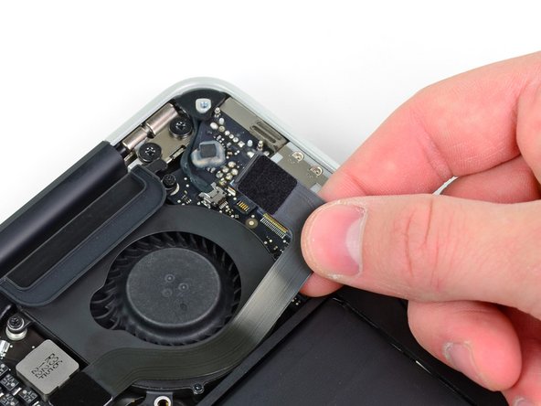
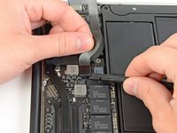
Use the flat end of a spudger to pry the I/O board cable connector upward out of its socket on the I/O board.
-
-
-
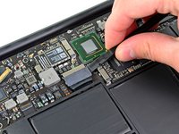
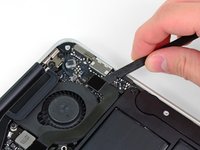
The following connector has an especially deep socket. Use care when disconnecting it.
-
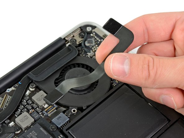
While gently pulling the I/O board cable upward near its connection to the logic board, use the tip of a spudger to pry upward on alternating sides of the connector to help "walk" it out of its socket.
-
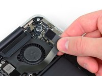
Remove the I/O board cable.
-


To reassemble your device, follow these instructions in reverse order.
Cancel: I did not complete this guide.
4 other people completed this guide.


1 Guide Comment
You only show the basic part of the removal. You do not show how to actually remove that board. You should have shown more steps.