Introduction
This guide will help give direction to properly remove the RAM and access the motherboard of your HP Pavilion Wave Desktop PC. Tools required for this removal include Phillips and Torx head screwdrivers, metal and plastic prying tools, and a magnetic arrangement pad.
What you need
-
-
Remove the three rubber footings by prying from the bottom cover using the plastic opening tool.
-
-
-
-
Remove the three 24 mm screws that connect the top cover to the chasis inside the HDD compartment using theTorx #15 screwdriver (an extension and torque lever might be useful).
-
-
-
Disconnect the microphone computer chip from the internal components by first peeling away the black adhesive holding the wires to the chassis and gently pulling the chip and wires from its connection.
This is the wifi module, not a "microphone computer chip." The wifi module does not need to be removed, the antenna leads can be disconnected, leaving the module attached to the motherboard.
-
-
-
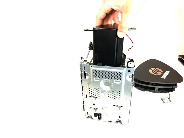
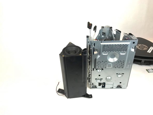
Remove the top chassis cover from the main chassis using the Torx Head #15 screwdriver to remove the nine 24 mm screws and then use the metal prying tool to pry the top chassis cover from the clips holding it to the main chassis and lift carefully away from internal components.
-
-
-
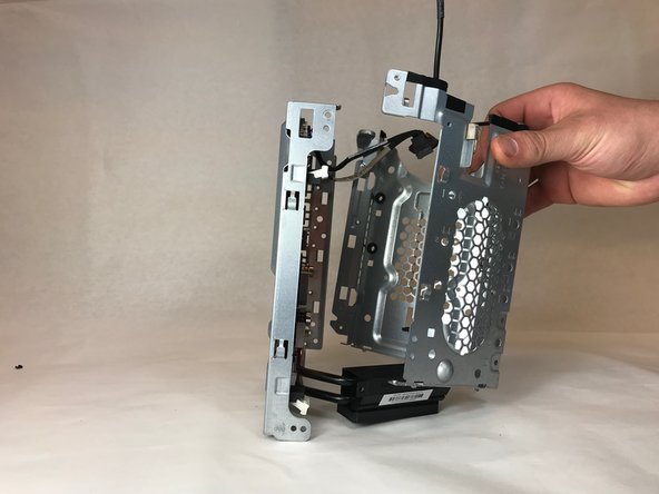
Remove the memory cover by removing the single 24 mm screw holding it to the main chassis using the Torx Head #15 screwdriver and sliding it up and out of its locking clips.
-
-
-
Remove the fan by removing the three 23 mm silver screws that hold the fan to the chassis using a Phillips Head #0 screwdriver.
Removal of the fan is only required if the fan needs to be replaced. Note there are two positions for fan mounting, depending on the heatsink size. The fan must always press against the heatsink.
-
-
-
Remove the heatsink from the chassis by using the Philips Head #2 screwdriver to remove two 24 mm screws.
-
-
-
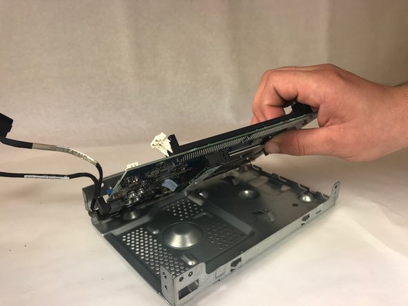
Remove the motherboard from the chassis by removing four 24 mm screws (two on front and two on back) using the Torx Head #15 screwdriver and gently lifting out and away from metal chassis.
Additional note on reassembly, be sure to angle the board and insert the ports under the grounding tabs on the chassis. Make sure not to accidently insert the grounding tab into the port, as it will damage the port.
-


To reassemble your device, follow these instructions in reverse order.
To reassemble your device, follow these instructions in reverse order.
Cancel: I did not complete this guide.
2 other people completed this guide.
Team

Idaho State University, Team S4-G3, Watkins Fall 2017 Member of Idaho State University, Team S4-G3, Watkins Fall 2017
ISU-WATKINS-F17S4G3
4 Members
5 Guides authored
2 Comments
Perfect unmount description, exept one point no. Sep 9 .. two screws are below the dard drive cover, one need a longer screwdriver shaft to open.
Where can I buye a mainboard replacement, I assume the exiting display controller is defect.
Thanks for your support.
Martin
Pauli.At.Mb@gmail.com
Step 6 what is the wire on top for