
Free Shipping on Domestic Orders $75+

HP Mini 1000 LCD Assembly Replacement

What you need

  1. HP Mini 1000 LCD Assembly Replacement, Battery: step 1, image 1 of 2 HP Mini 1000 LCD Assembly Replacement, Battery: step 1, image 2 of 2
    • With the case closed, place the Mini 1000 top-side down on a flat surface.

    • Push both of the battery release latches toward each other.

    Ask FixBot
  2. HP Mini 1000 LCD Assembly Replacement: step 2, image 1 of 1
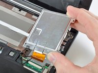
    • Lift the battery out of the Mini 1000 from the edge closest to the release latches.

    Ask FixBot
  3. HP Mini 1000 LCD Assembly Replacement, Keyboard: step 3, image 1 of 1
    • Remove the following two screws:

    • One 6 mm Phillips screw

    • One 4 mm Phillips screw

    Ask FixBot
  4. HP Mini 1000 LCD Assembly Replacement: step 4, image 1 of 3 HP Mini 1000 LCD Assembly Replacement: step 4, image 2 of 3 HP Mini 1000 LCD Assembly Replacement: step 4, image 3 of 3
    • To facilitate the removal of the keyboard, it is recommended to push the keyboard outwards with one hand through the opening (highlighted in the third picture) located on the backside of the Mini 1000.

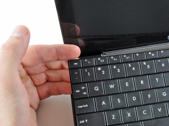
    • While pushing through the opening with one hand, grasp the left upper edge with the other hand and slightly pull the keyboard towards you.

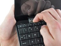
    • Once an opening has been established, grasp the keyboard and slowly lift it upwards along the upper perimeter of the top edge.

    Ask FixBot
  5. HP Mini 1000 LCD Assembly Replacement: step 5, image 1 of 1
    • Lift the keyboard out of the upper case, minding the cable that is still connecting it to the motherboard.

    Ask FixBot
  6. HP Mini 1000 LCD Assembly Replacement: step 6, image 1 of 1
    • Use your fingernail or the flat end of a spudger to flip up the retaining flap on the keyboard cable ZIF socket.

    • Be sure you are prying up on the retaining flap, not the socket itself.

    • Pull the cable out of its socket and remove the keyboard.

    Ask FixBot
  7. HP Mini 1000 LCD Assembly Replacement, Hard Drive: step 7, image 1 of 2 HP Mini 1000 LCD Assembly Replacement, Hard Drive: step 7, image 2 of 2
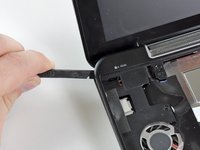
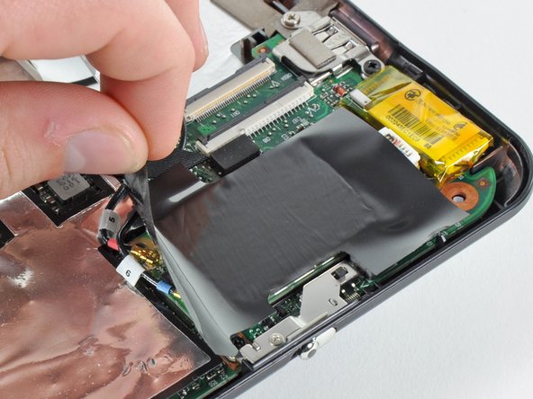
    • Use your fingernail or the flat end of a spudger to flip up the retaining flap on the SIM card ribbon cable ZIF socket.

    • Be sure you are prying up on the retaining flap, not the socket itself.

    • Pull the SIM card ribbon cable out of its socket and peel it off the top of the hard drive enclosure.

    Ask FixBot
  8. HP Mini 1000 LCD Assembly Replacement: step 8, image 1 of 1
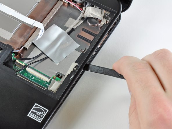
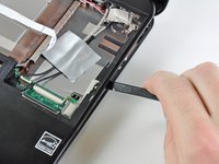
    • Use your fingernail or the flat end of a spudger to flip up the retaining flap on the hard drive cable ZIF socket.

    • Be sure you are prying up on the retaining flap, not the socket itself.

    Ask FixBot
  9. HP Mini 1000 LCD Assembly Replacement: step 9, image 1 of 1
    • Remove the two 4.5 mm Phillips screws securing the hard drive to the lower case.

    Ask FixBot
  10. HP Mini 1000 LCD Assembly Replacement: step 10, image 1 of 2 HP Mini 1000 LCD Assembly Replacement: step 10, image 2 of 2
    • Lift the hard drive up and out of the lower case, being careful not to damage its cable in the process.

    Ask FixBot
  11. HP Mini 1000 LCD Assembly Replacement, Upper Case: step 11, image 1 of 1
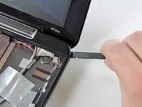
    • Using the sharp tip of a spudger, pry and remove the four plastic screw covers from the underside of the HP Mini 1000.

    • There are three different variations of the covers:

    • The two bottom covers are short in height and are notched to prevent incorrect insertion

    • The upper right cover is taller in height and is notched.

    • The upper left cover is taller in height and is not notched.

    Ask FixBot
  12. HP Mini 1000 LCD Assembly Replacement: step 12, image 1 of 1
    • Remove the four 7 mm Phillips screws that secure the upper case to the lower case.

    Ask FixBot
  13. HP Mini 1000 LCD Assembly Replacement: step 13, image 1 of 1
    • Flip the computer over and open the display.

    • Remove the two 4.5 mm Phillips screws securing the upper case to the lower case.

    Ask FixBot
  14. HP Mini 1000 LCD Assembly Replacement: step 14, image 1 of 2 HP Mini 1000 LCD Assembly Replacement: step 14, image 2 of 2
    • Wedge the flat end of a spudger in between the upper case and lower case near the bottom right corner of the display.

    • Carefully pry and rock the spudger upwards to create a small gap between the upper case and lower case.

    • Continue the previously described motion along the right edge of the upper case to release the clips securing the upper case to the lower case.

    Ask FixBot
  15. HP Mini 1000 LCD Assembly Replacement: step 15, image 1 of 2 HP Mini 1000 LCD Assembly Replacement: step 15, image 2 of 2
    • Repeat the same procedure as mentioned in the previous step to release the clips along the left side of the upper case.

    Ask FixBot
  16. HP Mini 1000 LCD Assembly Replacement: step 16, image 1 of 1
    • Grasp the upper case and carefully lift it slightly upwards, freeing it from any remaining clips.

    • The upper case is still attached via the TouchPad ribbon cable that is connected to the motherboard. Do not remove it completely just yet.

    Ask FixBot
  17. HP Mini 1000 LCD Assembly Replacement: step 17, image 1 of 1
    • Lay the upper case on top of the upper portion of the motherboard.

    • Use your fingernail or the flat end of a spudger to flip up the retaining flap on the TouchPad cable ZIF socket.

    • Be sure you are prying up on the retaining flap, not the socket itself.

    • Pull the TouchPad ribbon cable out of its socket.

    • Remove the upper case from the HP Mini 1000.

    Ask FixBot
  18. HP Mini 1000 LCD Assembly Replacement, Wi-Fi Board: step 18, image 1 of 1
    • If present, peel the sticker up off the top of the Wi-Fi board to reveal the Wi-Fi antenna connectors.

    Ask FixBot
  19. HP Mini 1000 LCD Assembly Replacement: step 19, image 1 of 3 HP Mini 1000 LCD Assembly Replacement: step 19, image 2 of 3 HP Mini 1000 LCD Assembly Replacement: step 19, image 3 of 3
    • Pry the Wi-Fi antenna connectors (2 total) up off the Wi-Fi board.

    • During reassembly, remember to correctly connect the antenna cables to their respective terminals. The green labeled antenna is connected to the "MAIN" terminal and the white labeled antenna is connected to the "AUX" terminal.

    Ask FixBot
  20. HP Mini 1000 LCD Assembly Replacement: step 20, image 1 of 1
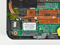
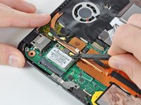
    • Remove the single 3 mm Phillips screw securing Wi-Fi board to the motherboard.

    Ask FixBot
  21. HP Mini 1000 LCD Assembly Replacement: step 21, image 1 of 1
    • Upon removing the Phillips screw that secures the Wi-Fi board to the motherboard, the Wi-Fi board should pop up from its top side nearest the antenna sockets.

    • Grasp the Wi-Fi board and lift it straight away from its socket on the motherboard.

    Ask FixBot
  22. HP Mini 1000 LCD Assembly Replacement, Heat Sink: step 22, image 1 of 1
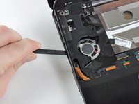
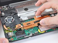
    • Remove the two 2.5 mm Phillips screws securing the heat sink to the motherboard.

    Ask FixBot
  23. HP Mini 1000 LCD Assembly Replacement: step 23, image 1 of 2 HP Mini 1000 LCD Assembly Replacement: step 23, image 2 of 2
    • Carefully lift the heat sink off the face of the motherboard and de-route the curved section from next to the fan.

    • Before reinstalling the heat sink, be sure to apply a new layer of thermal paste to the CPU. We have a thermal paste guide that makes it easy.

    • Only apply a new layer of thermal paste to the face of the CPU. The CPU is the large processor located closest to the fan.

    Ask FixBot
  24. HP Mini 1000 LCD Assembly Replacement, Display Assembly: step 24, image 1 of 2 HP Mini 1000 LCD Assembly Replacement, Display Assembly: step 24, image 2 of 2
    • If present, carefully remove the large piece of black adhesive film covering the Wi-Fi board.

    Ask FixBot
  25. HP Mini 1000 LCD Assembly Replacement: step 25, image 1 of 2 HP Mini 1000 LCD Assembly Replacement: step 25, image 2 of 2
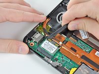
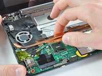
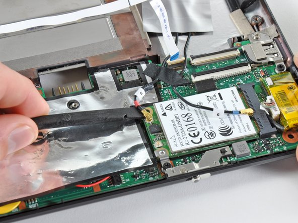
    • Use the flat end of a spudger to pry both antenna connectors up from their sockets on the Wi-Fi board.

    Ask FixBot
  26. HP Mini 1000 LCD Assembly Replacement: step 26, image 1 of 1
    • If present, remove the pieces of tape securing the Wi-Fi antenna cables to the upper case.

    Ask FixBot
  27. HP Mini 1000 LCD Assembly Replacement: step 27, image 1 of 1
    • If present, carefully remove the large piece of black adhesive film from the area surrounding the fan.

    Ask FixBot
  28. HP Mini 1000 LCD Assembly Replacement: step 28, image 1 of 1
    • If present, remove the several pieces of black cloth tape securing the cables to the upper case near the fan.

    Ask FixBot
  29. HP Mini 1000 LCD Assembly Replacement: step 29, image 1 of 2 HP Mini 1000 LCD Assembly Replacement: step 29, image 2 of 2
    • Use the flat end of a spudger to disconnect each of the following connectors from their respective sockets:

    • Speaker cable

    • Microphone cable

    • Fan cable

    • Power cable

    • Display data cable

    • Push the connectors out of their sockets parallel to the face of the motherboard toward the display assembly. Do not lift up on the cables as you disconnect them, especially the display data cable, as their sockets may break off the motherboard.

    Ask FixBot
  30. HP Mini 1000 LCD Assembly Replacement: step 30, image 1 of 1
    • If present, peel back the strip of white cloth tape highlighted in red to reveal a display screw.

    Ask FixBot
  31. HP Mini 1000 LCD Assembly Replacement: step 31, image 1 of 1
    • Remove the single 5 mm Phillips screw securing the right display hinge to the lower case.

    Ask FixBot
  32. HP Mini 1000 LCD Assembly Replacement: step 32, image 1 of 1
    • Remove the two 5 mm Phillips screws securing the left display hinge to the lower case.

    Ask FixBot
  33. HP Mini 1000 LCD Assembly Replacement: step 33, image 1 of 2 HP Mini 1000 LCD Assembly Replacement: step 33, image 2 of 2
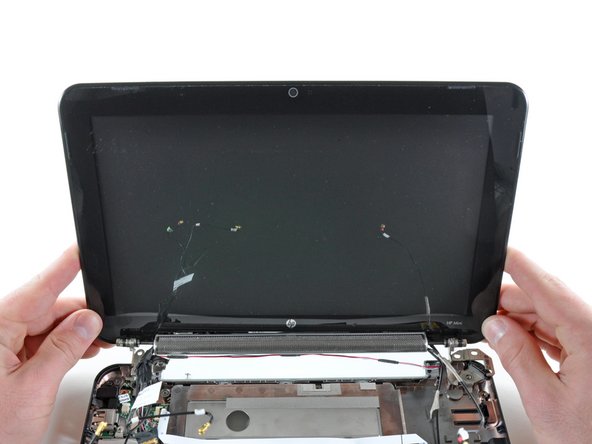
    • Lift the display out of the lower case, minding any cables that may get caught.

    Ask FixBot
  34. HP Mini 1000 LCD Assembly Replacement, Speaker Grill: step 34, image 1 of 2 HP Mini 1000 LCD Assembly Replacement, Speaker Grill: step 34, image 2 of 2
    • Use the edge of a plastic opening tool to pry the left side of the speaker grill away from the display assembly.

    • Be careful not to apply too much pressure to the display glass.

    Ask FixBot
  35. HP Mini 1000 LCD Assembly Replacement: step 35, image 1 of 1
    • Continue prying along the center of the speaker grill.

    Ask FixBot
  36. HP Mini 1000 LCD Assembly Replacement: step 36, image 1 of 2 HP Mini 1000 LCD Assembly Replacement: step 36, image 2 of 2
    • Pry the right side of the speaker grill away from the display assembly.

    Ask FixBot
  37. HP Mini 1000 LCD Assembly Replacement: step 37, image 1 of 1
    • Remove the speaker grill.

    Ask FixBot
  38. HP Mini 1000 LCD Assembly Replacement, Speaker Assembly: step 38, image 1 of 2 HP Mini 1000 LCD Assembly Replacement, Speaker Assembly: step 38, image 2 of 2
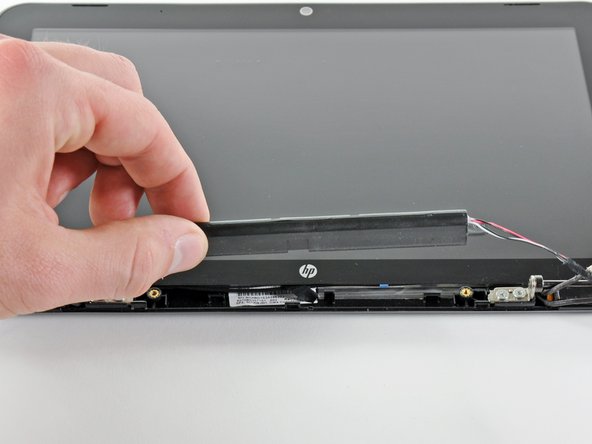
    • Remove the two 4.5 mm Phillips screws securing the speaker assembly to the display.

    • Remove the speaker assembly.

    Ask FixBot
  39. HP Mini 1000 LCD Assembly Replacement, Front Display Bezel: step 39, image 1 of 1
    • In the following steps you will pry the front display bezel off the rear section of the display. The locations of the retaining clips are highlighted in red.

    Ask FixBot
  40. HP Mini 1000 LCD Assembly Replacement: step 40, image 1 of 2 HP Mini 1000 LCD Assembly Replacement: step 40, image 2 of 2
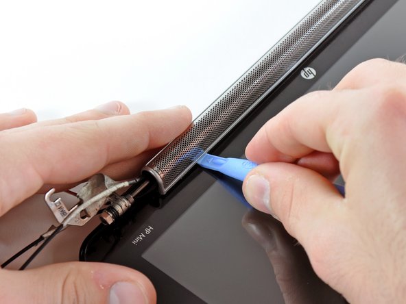
    • Use the edge of a plastic opening tool to pry up the front display bezel near the right display hinge.

    Ask FixBot
  41. HP Mini 1000 LCD Assembly Replacement: step 41, image 1 of 2 HP Mini 1000 LCD Assembly Replacement: step 41, image 2 of 2
    • Continue prying to release the clips attaching the front display bezel to the right side of the display's rear section.

    Ask FixBot
  42. HP Mini 1000 LCD Assembly Replacement: step 42, image 1 of 2 HP Mini 1000 LCD Assembly Replacement: step 42, image 2 of 2
    • Continue prying up the front display bezel along the top edge of the display.

    Ask FixBot
  43. HP Mini 1000 LCD Assembly Replacement: step 43, image 1 of 2 HP Mini 1000 LCD Assembly Replacement: step 43, image 2 of 2
    • Finally, use a plastic opening tool to release the retaining clips along the left side and bottom left corner of the display.

    Ask FixBot
  44. HP Mini 1000 LCD Assembly Replacement: step 44, image 1 of 1
    • Remove the front display bezel from the rest of the display assembly.

    Ask FixBot
  45. HP Mini 1000 LCD Assembly Replacement, Camera Board Cable: step 45, image 1 of 1
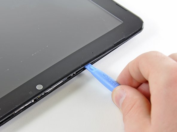
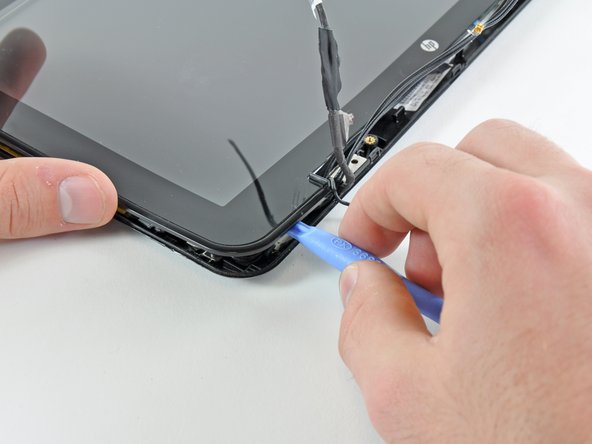
    • Use the sharp end of a spudger to flip up the plastic flap that rests on top of the camera board cable ZIF socket.

    Ask FixBot
  46. HP Mini 1000 LCD Assembly Replacement: step 46, image 1 of 2 HP Mini 1000 LCD Assembly Replacement: step 46, image 2 of 2
    • Use your fingernail or the sharp end of a spudger to flip up the retaining flap on the camera board cable ZIF socket.

    • Be sure you are prying up on the retaining flap, not the socket itself.

    • Pull the camera board ribbon cable out of its socket.

    Ask FixBot
  47. HP Mini 1000 LCD Assembly Replacement, LCD Assembly: step 47, image 1 of 1
    • If present, peel back the three pieces of cloth tape highlighted in red.

    • If present, remove the small strip of black cloth tape highlighted in orange.

    Ask FixBot
  48. HP Mini 1000 LCD Assembly Replacement: step 48, image 1 of 1
    • Remove the nine 3 mm Phillips screws securing the LCD to the rear display bezel.

    Ask FixBot
  49. HP Mini 1000 LCD Assembly Replacement: step 49, image 1 of 1
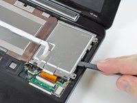
    • Lift the lower right corner of the LCD enough to de-route the antenna cables from its frame.

    Ask FixBot
  50. HP Mini 1000 LCD Assembly Replacement: step 50, image 1 of 1
    • Lift the left edge of the LCD out of the rear display bezel and de-route the cables from the brackets along the left side.

    Ask FixBot
  51. HP Mini 1000 LCD Assembly Replacement: step 51, image 1 of 1
    • Remove the LCD from the rear display bezel.

    • If your new LCD has no brackets included, swap the brackets from the old LCD to your new one.

    Ask FixBot
Conclusion

To reassemble your device, follow these instructions in reverse order.

One other person completed this guide.

1 Guide Comment

Do we really need to take that much off to just replace the screen? I've never done this before and I have no idea what is going on.

Lycan - Reply Share

Add Comment

View Statistics:

Past 24 Hours: 1

Past 7 Days: 8

Past 30 Days: 78

All Time: 9,439