Introduction
The Fujtsu Lifebook Model a6110 RAM is what's going to determine your laptop’s speed. Once it begins to slow down or crash without warning, this signals that you will need to remove and replace your random access memory (RAM). Whether you are replacing or upgrading your system's memory, this easy-to-use guide demonstrates the process in six steps. Due to the electrical components, here's a link for tips and demonstrations on how to protect yourself prior to starting our steps in the guide.
What you need
-
-
Flip your laptop so that the bottom of the laptop is facing up and the hinges of the screen are closest to you.
 Ask FixBot
-
-
-
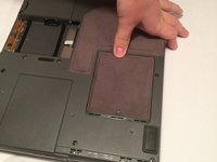
To remove the battery, place your fingers underneath the two clips and simultaneously lift them up while pulling the cover towards you.
-
-
-
-
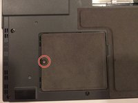
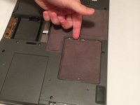
The RAM compartment will be located near the bottom-left corner of your lifebook. The compartment is behind the cover held in place by a 6 mm screw.
-
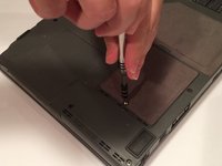
Using a Phillips #1 screwdriver, remove the 6 mm screw from the RAM compartment on the bottom-left corner of the rear cover.
-
-
-
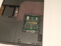
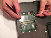
Simultaneously pull each metal and plastic clip away from the center of the RAM stick.
-


To reassemble your device, follow these instructions in reverse order.
Team

UMass Dartmouth, Team 3-2, Isaacson Fall 2016 Member of UMass Dartmouth, Team 3-2, Isaacson Fall 2016
UMASSD-ISAACSON-F16S3G2
3 Members
10 Guides authored