-
-
-
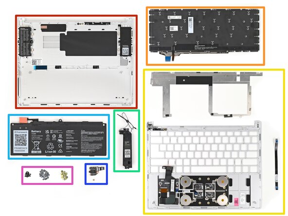
Bottom Cover Kit
-
Keyboard
-
Input Cover Frame (including the Keyboard Bracket and Fingerprint Reader Cable)
-
Speaker Kit
-
Battery
-
Audio Board Kit
-
Fastener Kit – Input Cover and Keyboard (only the Keyboard and Keyboard Bracket screws are needed—the rest can be kept as spares)
 Ask FixBot
-
-
-
Separate the Speakers from each other if they're attached.
-
-
-
Place the left Speaker into its slot on the Bottom Cover, making sure it's aligned with its screw posts and threaded through its alignment peg.
-
-
-
Use your Framework Screwdriver to tighten the two T5 Torx screws on each Speaker (4 total).
-
-
-
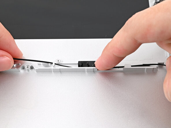
Starting from the right Speaker, press the speaker cable into its metal and plastic clips on the Bottom Cover.
-
-
-
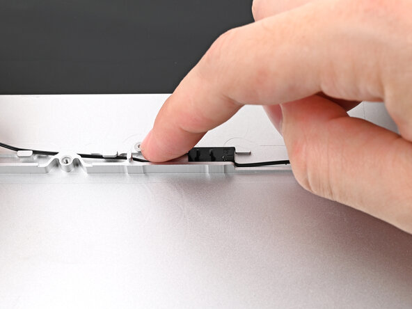
If you're having difficulty pressing the speaker cable into its plastic clips, twist the cable so it's vertical and use the flat end of your Framework Screwdriver to press it down.
-
-
-
Repeat the previous two steps for the section of Speaker Cable near the left Speaker.
-
-
-
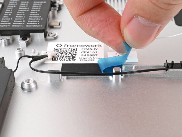
Remove the blue liner from the black tape near the left Speaker.
-
-
-
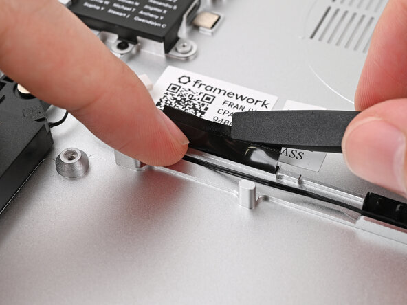
Slide the flat end of your Framework Screwdriver under the black tape and separate one of its long edges from the Chassis.
-
-
-
While holding the tape out of the way, lay the Speaker Cable into the channel underneath it.
-
Press the tape over the Speaker Cable to adhere it to the Chassis.
-
-
-
Before continuing, check the pins on the Battery socket and make sure they aren't bent.
-
-
-
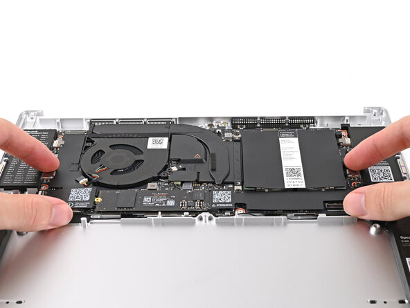
Grab the Mainboard by its edges and place it into the Bottom Cover and onto its alignment pegs.
-
-
-
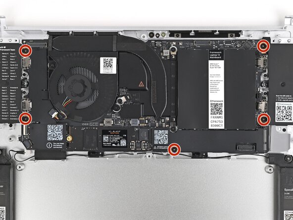
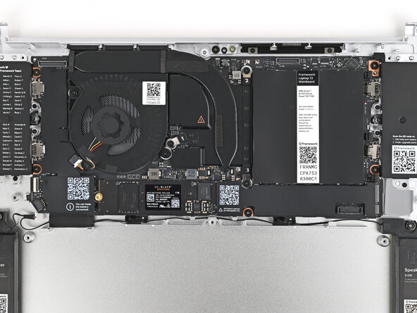
Use your Framework Screwdriver to install the five 1.5 mm‑long T5 Torx screws securing the Mainboard.
-
-
-
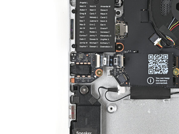
Angle the left edge of the Audio Board downward and slide the headphone jack through its hole in the Bottom Cover.
-
Align the screw hole in the Audio Board with its post and press it flat to the Bottom Cover.
-
-
-
Use your Framework Screwdriver to install the 3.0 mm‑long T5 Torx screw securing the Audio Board.
-
-
-
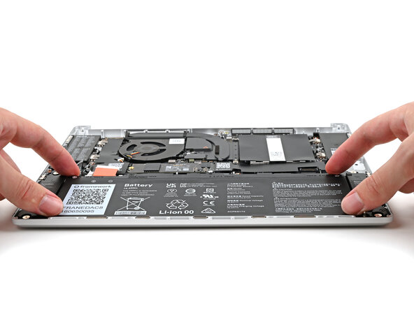
Insert the Battery into its cutout, making sure its plastic tabs are slotted into the Bottom Cover.
-
-
-
Use your Framework Screwdriver to tighten the three captive T5 Torx screws securing the Battery.
-
-
-
-
Place the Top Cover on its two sets of alignment pegs on the Bottom Cover.
-
Make sure all of the cables are above the Bottom Cover before continuing.
-
-
-
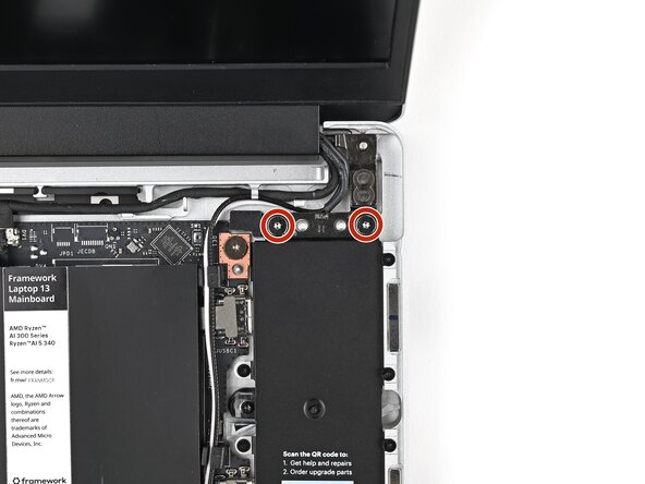
While supporting the Top Cover with one hand, use your Framework Screwdriver to install two 4.0 mm‑long T5 Torx screws on each Hinge connected to the Bottom Cover (four total).
-
-
-
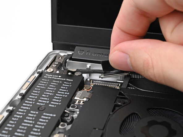
Place the Display eDP Cable into its slot on the Bottom Cover.
-
-
-
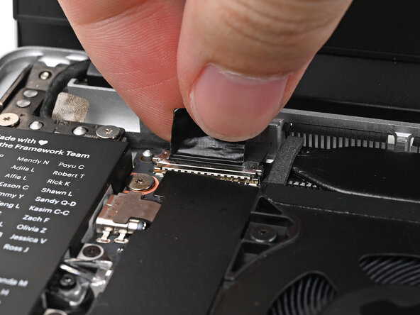
Press the Display eDP Cable connector straight down into its socket to connect it.
-
-
-
Press the grounding tape onto the left Hinge to adhere it.
-
-
-
Slide the Audio Board cable straight into its socket.
-
-
-
Use the flat end of your Framework Screwdriver, or a clean fingernail, to press down the locking tab on the Audio Board ZIF connector.
-
-
-
Use your finger to guide the Webcam Cable into its metal pegs on the Bottom Cover.
-
-
-
Press the Webcam Cable connector straight down into its socket to connect it.
-
-
-
Use your finger to press the Antenna Cables into their metal clip on the Bottom Cover.
-
Rotate the cables around the raised corner at the top right of the Mainboard so they point towards the Wi-Fi module.
-
-
-
Use your Framework Screwdriver to loosen the captive T5 Torx screw securing the Wi-Fi module cover.
-
-
-
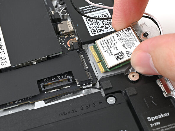
Align the Wi-Fi module's gold contacts and notch with the socket on the Mainboard.
-
Insert the Wi-Fi module into the socket at a shallow angle. The gold contacts should mostly be covered by the socket.
-
-
-
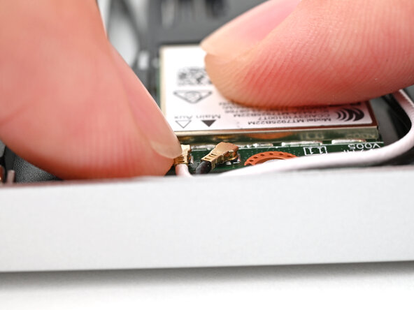
Hold the Wi-Fi module down with your finger.
-
Position the black antenna cable connector over the Wi-Fi module's coaxial socket indicated by the black arrow.
-
Use your finger to press the connector into place. You should feel a faint click, and the cable will stay attached to the socket by itself.
-
Repeat the procedure with the white antenna cable.
-
-
-
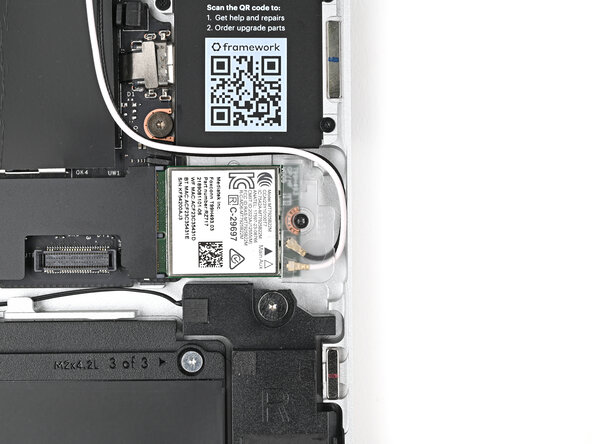
Use your Framework Screwdriver to tighten the captive T5 Torx screw securing the Wi-Fi module.
-
-
-
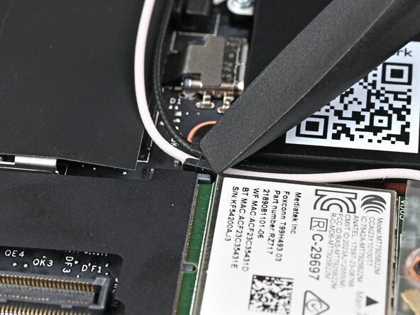
Use the flat end of your Framework Screwdriver to press the two Antenna Cables into their rubber clips on the Mainboard.
-
-
-
Use your fingers to align the Battery connector with its socket and slide it straight in to reconnect the Battery.
-
-
-
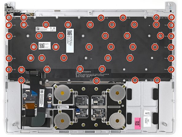
Use your Framework Screwdriver to install the forty-six 1.2 mm‑long black PH0 screws securing the Keyboard.
-
-
-
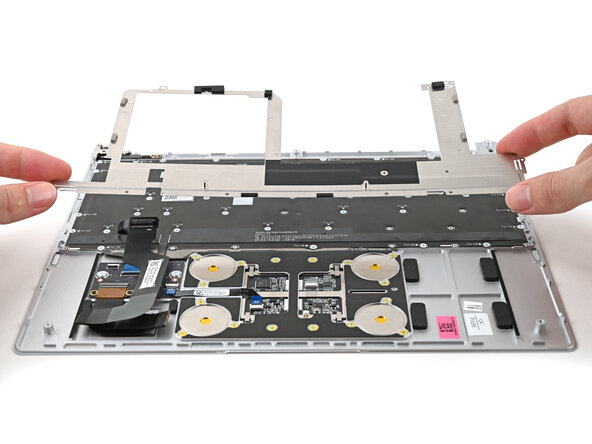
Place the Keyboard Bracket onto its alignment pegs.
-
-
-
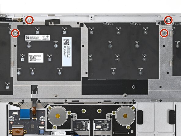
Use your Framework Screwdriver to install the twenty 1.3 mm‑long silver PH0 screws securing the Keyboard Bracket.
-
-
-
Use the flat end of your Framework Screwdriver, or a clean fingernail, to lift up the locking tab on the Fingerprint Reader ZIF connector located on the Fingerprint Reader board.
-
-
-
Slide the Fingerprint Reader Cable straight into its socket.
-
-
-
Use the flat end of your Framework Screwdriver, or a clean fingernail, to press down the locking tab on the Fingerprint Reader ZIF connector.
-
-
-
Repeat the previous three steps to connect the Fingerprint Reader Cable on the Hub Board.
-
-
-
Position the Input Cover, keyboard down, on top of the laptop so it just covers the Battery.
-
-
-
Insert your finger into the Touchpad Cable press connector loop.
-
Align the press connector over its socket and press down with your finger.
-
-
-
Flip the Input Cover over the laptop and align the bottom edges.
-
-
-
Close the laptop and flip it over.
-
Use your Framework Screwdriver to tighten the five captive T5 Torx screws securing the Input Cover.
-
-
-
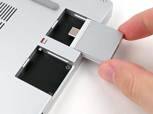
Slide an Expansion Card into an Expansion Card slot.
-
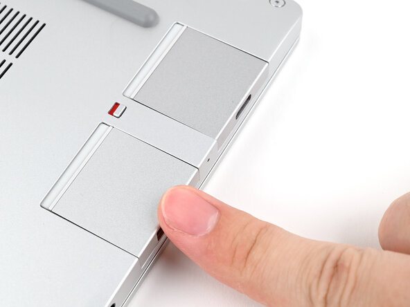
Repeat for the remaining Expansion Cards.
-
-
-
You've finished upgrading your Framework Laptop! Check out this page to update to the latest drivers, firmware, and software.
-
-

































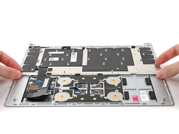
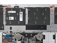


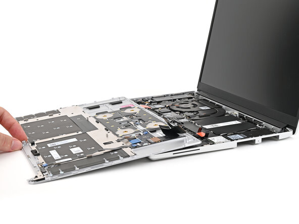


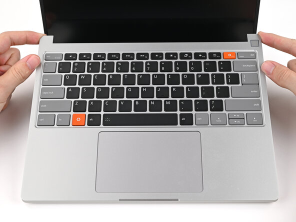







To reassemble your device, follow these instructions in reverse order.

