Free Shipping on Domestic Orders $75+

This teardown is not a repair guide. To repair your Twingo III, use our service manual.

    1. Engine Sensors and Probes, Knock sensor: step 1, image 1 of 2 Engine Sensors and Probes, Knock sensor: step 1, image 2 of 2
      • Location: Under the intake manifold.

      • Tightening torque: 20 N.m.

      • The service manual does not provide a tightening torque. The value given above corresponds to the torque recommended by Bosch for their knock sensors.

      Ask FixBot

      Add Comment

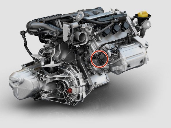
    2. Engine Sensors and Probes, Top Dead Center (TDC) Sensor: step 2, image 1 of 3 Engine Sensors and Probes, Top Dead Center (TDC) Sensor: step 2, image 2 of 3 Engine Sensors and Probes, Top Dead Center (TDC) Sensor: step 2, image 3 of 3
      • Location (JE3 0xx and DC0 transmissions): on the gearbox, towards the front side of the vehicle.

      • Replacement: see guide.

      • Torque: 10 N.m

      • Part number: 23 73 101 35R and/or 237312011R

      • The service manual does not provide a torque value. The one given above is identical to the camshaft sensor and other components using a screw of this size.

      Ask FixBot

      Add Comment

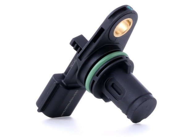
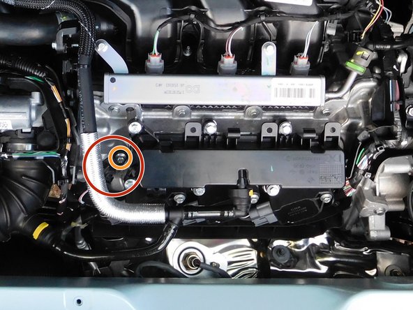
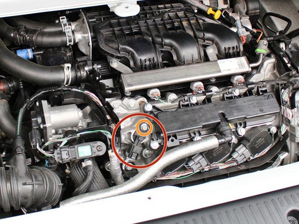
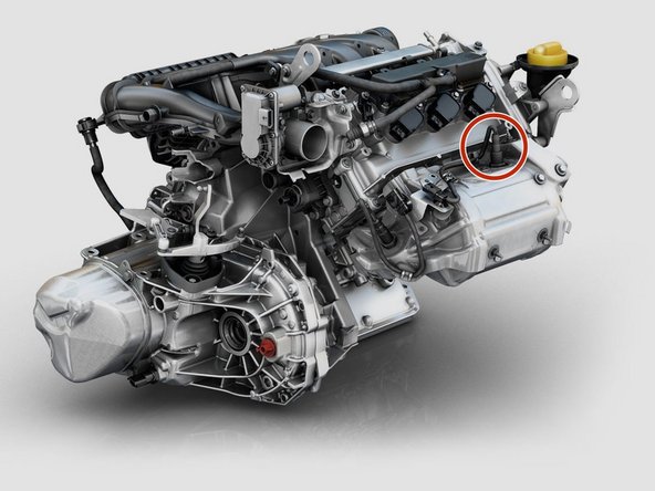
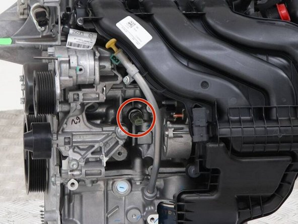
    3. Engine Sensors and Probes, Camshaft position sensor: step 3, image 1 of 3 Engine Sensors and Probes, Camshaft position sensor: step 3, image 2 of 3 Engine Sensors and Probes, Camshaft position sensor: step 3, image 3 of 3
      • Location (H4D and H4Bt): to the left of the oil vapor breather.

      • Torque: 10 N·m

      • The CMP sensor is magnetic and can therefore collect metal filings (from the oil) over time. Wiping the sensor to maintain optimal precision seems crucial.

      Ask FixBot

      Add Comment

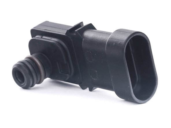
    4. Engine Sensors and Probes, Manifold Absolute Pressure (MAP) Sensor: step 4, image 1 of 2 Engine Sensors and Probes, Manifold Absolute Pressure (MAP) Sensor: step 4, image 2 of 2
      • The intake air pressure sensor (MAP sensor) measures the air pressure in the intake manifold. Using specific formulas, the ECU can calculate the amount of intake air and adjust fuel injection accordingly.

      • Because it is located after the oil vapor breather in the intake, deposits can clog it and disrupt its proper operation. Periodic cleaning is highly recommended.

      • Symptoms of clogging: Unstable and/or abnormal idle, vibrations, hesitation, loss of torque.

      Ask FixBot

      Add Comment

    5. Engine Sensors and Probes, Intake Air Temperature Sensor: step 5, image 1 of 1
      • Since air density varies with temperature, this sensor is critical for calculating the mass of air drawn into the engine and adjusting the fuel injection accordingly.

      Ask FixBot

      Add Comment

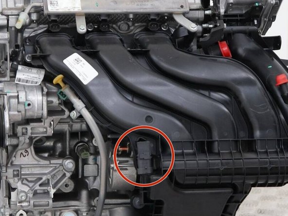
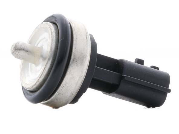
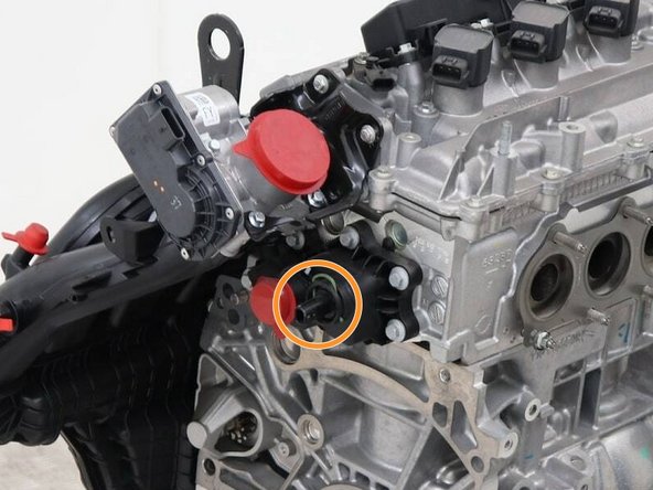
    6. Engine Sensors and Probes, Coolant temperature sensor: step 6, image 1 of 2 Engine Sensors and Probes, Coolant temperature sensor: step 6, image 2 of 2
      • Insert a comment.

      Ask FixBot

      Add Comment

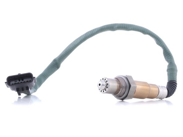
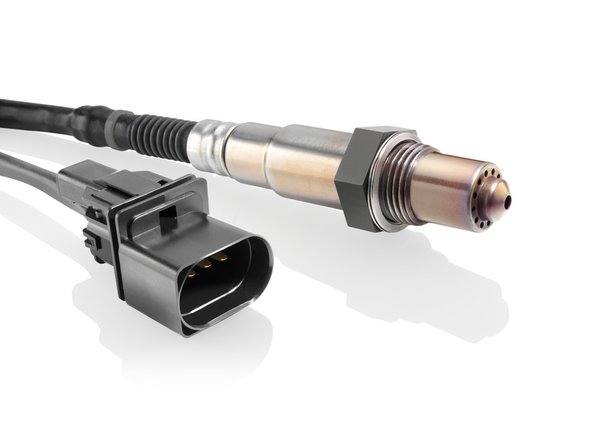
    7. Engine Sensors and Probes, Upstream lambda sensor (Bosch LSU ADV): step 7, image 1 of 2 Engine Sensors and Probes, Upstream lambda sensor (Bosch LSU ADV): step 7, image 2 of 2
      • The Bosch 0 258 027 00A upstream lambda sensor, type LSU ADV, is a planar ZrO2 wideband sensor. It is preheated and allows for precise lambda measurement in the lean, stoichiometric, and rich ranges.

      • Location: upstream of the catalytic converter.

      • The lambda value of the upstream sensor is interpreted based on current (amperage) and not voltage, unlike the downstream sensor and other sensors on the market.

      • This sensor is absolutely critical to the optimal operation of the engine, regardless of the fuel used. A malfunction will lead to a vicious cycle, further wearing it out while risking damage to other components, such as the catalytic converter, and causing carbon buildup in the engine.

      • Compatible fuels: Gasoline/Diesel/E85

      • Measurement range: lambda 0.65 to ∞

      • Torque: 40 to 60 Nm

      • Start-up time ≤ 5 s

      Ask FixBot

      Add Comment

    8. Engine Sensors and Probes, Downstream oxygen sensor (Bosch LSF-XF): step 8, image 1 of 2 Engine Sensors and Probes, Downstream oxygen sensor (Bosch LSF-XF): step 8, image 2 of 2
      • The Bosch 0 258 030 00L downstream oxygen sensor, type LSF-XF, is a ZrO2 narrow-band voltage-step sensor. It only allows for measurement within a very narrow range of the stoichiometric ratio. It is used to verify the proper operation of the catalytic converter.

      • Location: downstream of the catalytic converter.

      • Measurement range: lambda 0.93 to 1.15.

      Ask FixBot

      Add Comment

    9. Engine Sensors and Probes, Oil pressure switch ("sensor"): step 9, image 1 of 2 Engine Sensors and Probes, Oil pressure switch ("sensor"): step 9, image 2 of 2
      • This part does not provide any indication of the oil pressure. It only indicates whether the pressure is greater than or equal to 0.6 bar (a switch only has two states: ON/OFF).

      • The RTA specifies that the expected oil pressure for the H4D engine is 1.7 bar minimum at an engine speed between idle and 4,000 RPM. Above 4,000 RPM and up to the rev limiter, a minimum of 3.5 bar is expected.

      • The previously mentioned pressures are provided for an oil temperature of 80°C and with oil meeting the RTA specification (0-10W40, RN0700). These may vary, but will necessarily be higher when cold!

      • If the pressure drops below 0.6 bar, the oil pressure light on the dashboard will turn on, very late.

      Ask FixBot

      Add Comment

AntonioTwingo

Member since: 08/24/22

8,153 Reputation

45 Guides authored

0 Guide Comments

Add Comment

View Statistics:

Past 24 Hours: 2

Past 7 Days: 27

Past 30 Days: 137

All Time: 4,983