
15% Off Selected iFixit Tools — Limited Time
Free Shipping on Domestic Orders $75+

Disassembling the Circuit Board

What you need

  1. Disassembling the Circuit Board, Cracking the Case: step 1, image 1 of 1
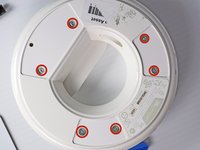
    • Turn the device upside down so that the three rubber pads are facing up.

    Ask FixBot

    Add Comment

  2. Disassembling the Circuit Board: step 2, image 1 of 1
    • Use a heat gun (set to low) to apply heat to one of the rubber pads until you can easily remove the pad. This step takes around 5-7 minutes.

    Ask FixBot

    Add Comment

  3. Disassembling the Circuit Board: step 3, image 1 of 1
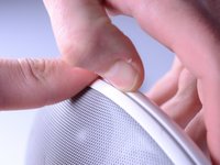
    • Remove the heated rubber pad with a plastic opening tool.

    • Repeat steps 2 and 3 for the two remaining rubber pads.

    Ask FixBot

    Add Comment

  4. Disassembling the Circuit Board: step 4, image 1 of 2 Disassembling the Circuit Board: step 4, image 2 of 2
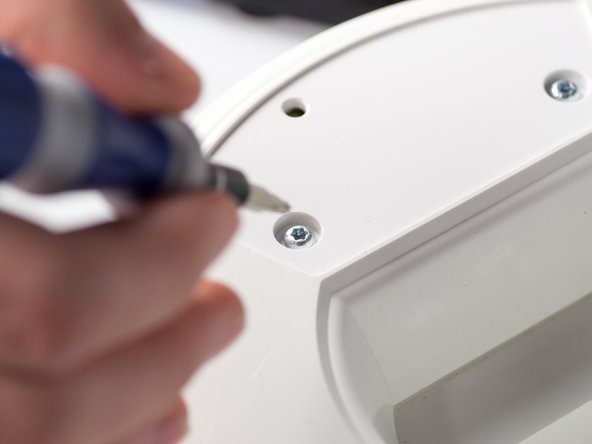
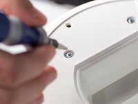
    • Remove the six 1cm T-10 torx screws on the bottom of the device (found under the rubber pads) using a T-10 Torx screwdriver.

    Ask FixBot

    Add Comment

  5. Disassembling the Circuit Board: step 5, image 1 of 3 Disassembling the Circuit Board: step 5, image 2 of 3 Disassembling the Circuit Board: step 5, image 3 of 3
    • Open the device along its seam.

    • Be careful when separating the device because there are wires connecting the two seperate halves.

    Ask FixBot

    Add Comment

  6. Disassembling the Circuit Board: step 6, image 1 of 1
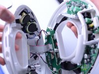
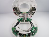
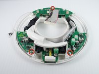
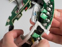
    • Disconnect the ribbon cable connector from the top half of the device by pulling outward and parallel to the connecting pins.

    Ask FixBot

    Add Comment

  7. Disassembling the Circuit Board: step 7, image 1 of 2 Disassembling the Circuit Board: step 7, image 2 of 2
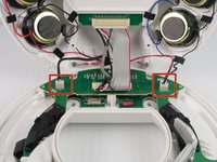
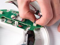
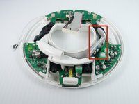
    • Locate and disconnect the two molex connectors found on either side of the ribbon cable connector on the bottom half of the device.

    Ask FixBot

    Add Comment

  8. Disassembling the Circuit Board, Circuit Board: step 8, image 1 of 2 Disassembling the Circuit Board, Circuit Board: step 8, image 2 of 2
    • Remove the three 1 cm T-10 Torx screws.

    Ask FixBot

    Add Comment

  9. Disassembling the Circuit Board: step 9, image 1 of 1
    • Carefully press out the white base tube and push up on the circuit board.

    • Note that there is a small wire connecting the circuit board to the base.

    Ask FixBot

    Add Comment

  10. Disassembling the Circuit Board: step 10, image 1 of 2 Disassembling the Circuit Board: step 10, image 2 of 2
    • Pull the white wire out of the hot glue.

    Ask FixBot

    Add Comment

  11. Disassembling the Circuit Board: step 11, image 1 of 3 Disassembling the Circuit Board: step 11, image 2 of 3 Disassembling the Circuit Board: step 11, image 3 of 3
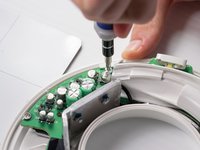
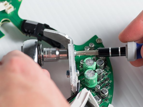
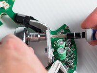
    • Unbolt the heatsink with a 5.5-mm socket and a Phillips PH1 screwdriver.

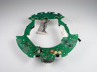
    • Remove the heat sink; it should detach from the bottom of the device.

    Ask FixBot

    Add Comment

  12. Disassembling the Circuit Board: step 12, image 1 of 3 Disassembling the Circuit Board: step 12, image 2 of 3 Disassembling the Circuit Board: step 12, image 3 of 3
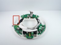
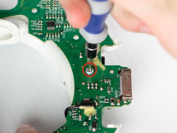
    • Remove the T-10 torx screw on the bottom of the device that attaches the base tube to the circuit board.

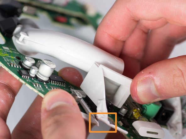
    • Turn the device so that the base tube is on top.

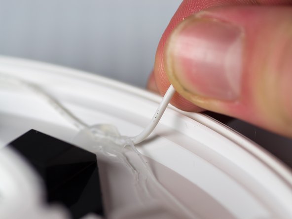
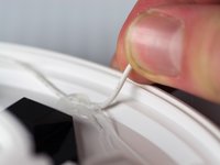
    • Remove the base tube by pulling up.

    • May need to cut the rubber adhesive between the base tube to the circuit board.

    Ask FixBot

    Add Comment

Conclusion

To reassemble your device, follow these steps in reverse order.

Cancel: I did not complete this guide.

2 other people completed this guide.

Janessa D Cabrera

Member since: 01/23/14

547 Reputation

4 Guides authored

Team

Cal Poly, Team 9-28, Maness Winter 2014 Member of Cal Poly, Team 9-28, Maness Winter 2014

CPSU-MANESS-W14S9G28

4 Members

10 Guides authored

0 Guide Comments

Add Comment

View Statistics:

Past 24 Hours: 1

Past 7 Days: 11

Past 30 Days: 58

All Time: 5,319