Free Shipping on Domestic Orders $75+

This translation was generated by a machine and has not been reviewed by a person yet. Speak this language? Review it.

Detectometer Assembly Guide

What you need

    1. Detectometer Assembly Guide, Detectometer Assembly Guide: step 1, image 1 of 3 Detectometer Assembly Guide, Detectometer Assembly Guide: step 1, image 2 of 3 Detectometer Assembly Guide, Detectometer Assembly Guide: step 1, image 3 of 3
      • gather all necessary equipment

      • 1 Arduino Mega

      • 1 detectometer shield

      • 1 energy shield + the battery

      Ask FixBot

      Add Comment

    2. Detectometer Assembly Guide: step 2, image 1 of 3 Detectometer Assembly Guide: step 2, image 2 of 3 Detectometer Assembly Guide: step 2, image 3 of 3
      • 1 screen

      • 1 Bluetooth module along with its small cable

      • 1 MicroSD card

      Ask FixBot

      Add Comment

    3. Detectometer Assembly Guide: step 3, image 1 of 3 Detectometer Assembly Guide: step 3, image 2 of 3 Detectometer Assembly Guide: step 3, image 3 of 3
      • 5 connectors

      • A case

      • the screws

      Ask FixBot

      Add Comment

    4. Detectometer Assembly Guide: step 4, image 1 of 3 Detectometer Assembly Guide: step 4, image 2 of 3 Detectometer Assembly Guide: step 4, image 3 of 3
      • Start by trimming the energy shield card using flush cutters flush with the blue connector

      • Cut the connector leads to leave approximately 7 mm

      Ask FixBot

      Add Comment

    5. Detectometer Assembly Guide: step 5, image 1 of 3 Detectometer Assembly Guide: step 5, image 2 of 3 Detectometer Assembly Guide: step 5, image 3 of 3
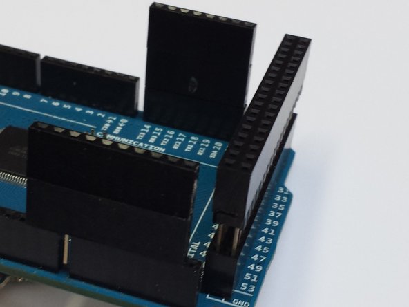
      • Insert the connectors into the Arduino, and stack them as shown in the first image; there should be no gap between them.

      • Connect the battery to the shield and insert it into the Arduino.

      • Once the operation is complete, check the alignment; the connectors should be at approximately the same level.

      Ask FixBot

      Add Comment

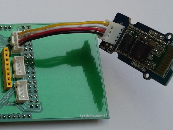
    6. Detectometer Assembly Guide: step 6, image 1 of 2 Detectometer Assembly Guide: step 6, image 2 of 2
      • Prepare the Detectomètre shield and connect the Bluetooth module to the input labeled as such

      • Insert the MicroSD card into the reader

      Ask FixBot

      Add Comment

    7. Detectometer Assembly Guide: step 7, image 1 of 2 Detectometer Assembly Guide: step 7, image 2 of 2
      • Be sure to route the base battery wires between the two connectors as shown in the second photo

      • Now insert the detectometer shield onto the base (arduino + energy shield + connectors)

      Ask FixBot

      Add Comment

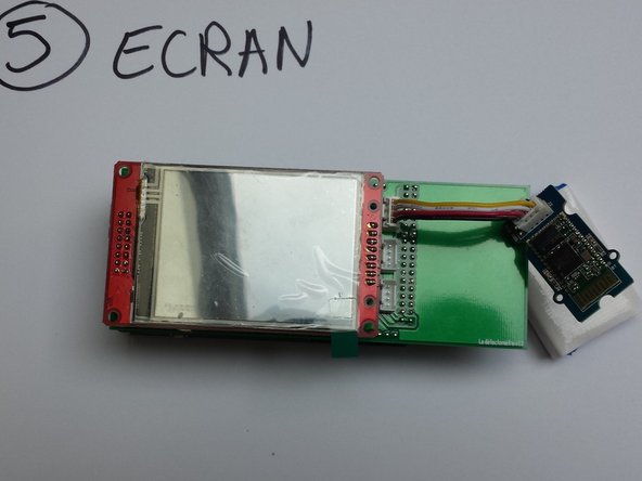
    8. Detectometer Assembly Guide: step 8, image 1 of 1
      • Insert the screen onto the yellow connectors

      • All that remains is to assemble the box

      Ask FixBot

      Add Comment

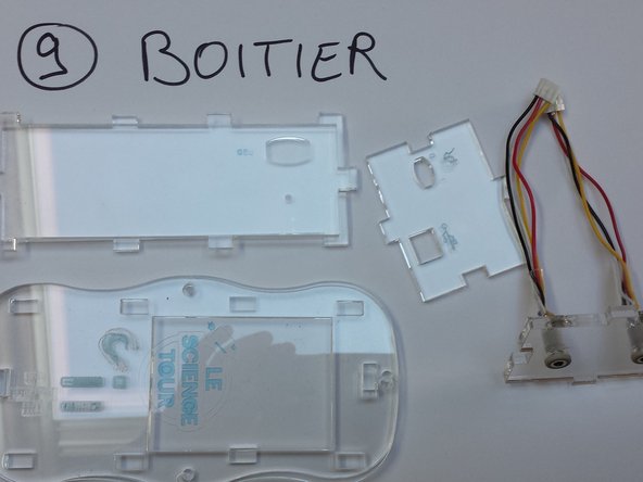
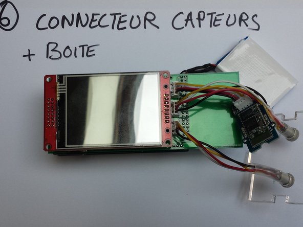
    9. Detectometer Assembly Guide: step 9, image 1 of 2 Detectometer Assembly Guide: step 9, image 2 of 2
      • Install the "sensor inputs" faceplate and connect the cables to the correct connectors

      • Route the 2 sensor cables on either side of the detector shield and position the faceplate as shown in the second photo

      Ask FixBot

      Add Comment

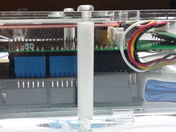
    10. Detectometer Assembly Guide: step 10, image 1 of 1
      • Once the box is assembled, position the white spacers + washer and screw them in

      • Don't forget the small washer! Otherwise, the box might break

      Ask FixBot

      Add Comment

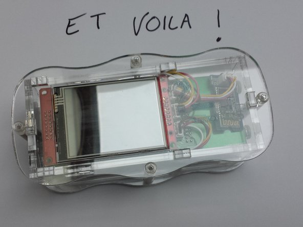
    11. Detectometer Assembly Guide: step 11, image 1 of 1
      • Congratulations! You have just assembled the detectometer!

      Ask FixBot

      Add Comment

Conclusion

To reassemble your device, follow these instructions in reverse order.

Cancel: I did not complete this guide.

One other person completed this guide.

julienrat

Member since: 03/29/14

166 Reputation

1 Guide authored

0 Guide Comments

Add Comment

View Statistics:

Past 24 Hours: 0

Past 7 Days: 5

Past 30 Days: 30

All Time: 363