Introduction
Connecting the cables from your power supply to your hardware components can be an arduous task. This guide will show you, step by step, how to connect your cables. This guide is best for custom-build PCs. Be aware of electrostatic discharge when interacting with the components of your PC. Wear an electrostatic discharge (ESD) bracelet to ground yourself and prevent shocking any of your PC components. You will need no other tools for this process, but cable ties may be used for organizational purposes
What you need
-
-
Red- Optional ATX Connector
-
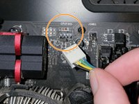
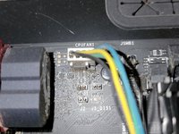
Orange- CPU Fan 1
-
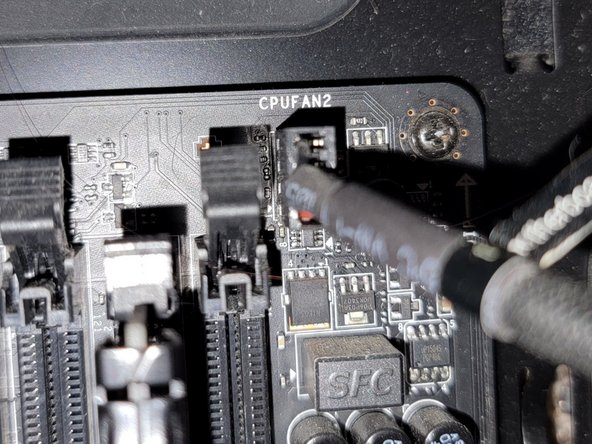
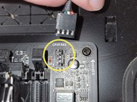
Yellow- CPU Fan 2
-
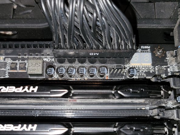
Green- Main ATX Connectors
-
Light Blue- GPU
-
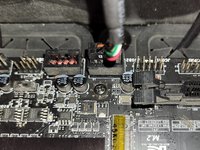
Blue- Panel Connectors
-
Pink- USB Connectors
-
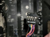
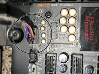
Black- HD Audio
-
-
-
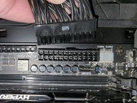
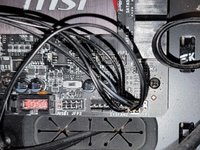
Connect the two separate six-pin segments to six pins each on the 12-pin PCIE port.
-
-
-
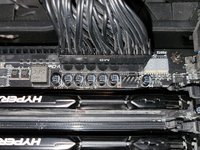
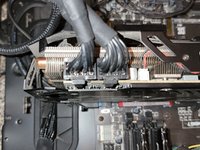
Connect the four pin segment to the four pin PCEI connector labeled "CPUFAN1."
-
-
-
-
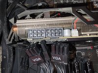
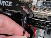
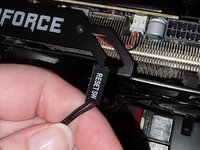
Connect both of the separate eight pin segments to each of the eight pin PCIE ports on the graphics card.
-
-
-
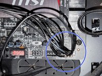
This PCIE port consists of eight pins, two rows of four.
-
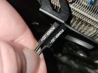
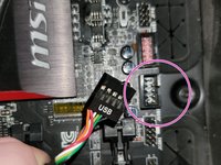
Connect the "Power LED+" pin to the pin at the top right corner.
-
Connect the "Power LED-" segment to the pin next to the "Power LED+" segment in the top row.
-
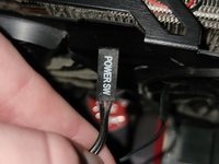
Connect the "Power SW" segment to the two pins on the left side of the top row of pins.
-
-
-
Connect the "HDD LED" segment to the two pins on the right side of the bottom row of pins.
-
Connect the "Reset SW" segment to the two pins on the left side of the bottom row of pins.
-


To disconnect the cable ties, follow these directions in reverse order.
Cancel: I did not complete this guide.
2 other people completed this guide.
