Introduction
If you need to to replace you the lens of your camera, we recommend that you use this guide.
What you need
-
-
If the initial shutter button dislodge does not work, we have to disassemble the camera.
-
On the bottom of the camera, use your thumb and push the battery lock up to open. The battery compartment door should then spring open and batteries will slide out.
-
-
-
Place the camera down so that the lens is facing up.
-
Next, use the Phillips #00 Precision Screwdriver to unscrew the inner most 4 mm phillips head screw. This will remove the door from the camera.
-
-
-
Remove the six 4 mm phillips head screws that are found on both the sides and bottom of the camera with the Phillips #00 Precision Screwdriver.
-
-
-
Slowly and gently pry open with your hands to separate the back case panel from the rest of the camera.
-
-
-
Unscrew the two 3 mm screws that are below the LCD Screen Mount with the Phillips #00 Precision Screwdriver.
-
Unscrew the top 4 mm screw with the Phillips #00 Precision Screwdriver.
-
-
-
Carefully lift and turnover the LCD Screen so that you are able to see the motherboard.
-
Carefully disconnect the LCD Screen ribbon cable away from its ZIF connector with your thumb and index finger. You must make sure to have your thumb and index finger cover as much of the ribbon's width and as close to the ZIF connector as possible without touching the motherboard while pulling the ribbon out.
-
-
-
-
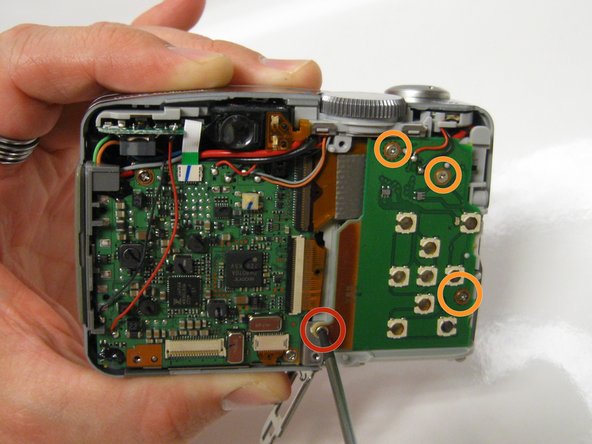
Remove the 3 mm phillips head screw that is between the circuit boards.
-
Remove the next three 3.5 mm phillips head screws that are on the button circuit board.
-
-
-
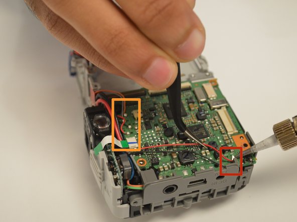
Use the spudger to unclip both wires from underneath the shutter button and settings dial housing unit.
-
-
-
Turn the camera over and unscrew 4.5 mm Phillips head screw to detach the shutter button and settings dial from the rest of the camera.
-
From the metal frame, unscrew the 3 mm Phillips screw head to begin to detachment of the battery housing unit.
-
-
-
Use the plastic opening tool to begin separating the button circuit board from the shutter button and settings dial housing unit.
-
Carefully disconnect the ribbon cable that is attached to the user buttons circuit board away from the ZIF connector that is attached to the motherboard.
-
Remove the user button circuit board.
-
-
-
Use the spudger to carefully remove the attached ribbon cable.
-
Be careful not to rip ribbon cable attached to motherboard out of the ZIF connector.
-
-
-
Unsolder all of the wires attached to the motherboard and move them aside with the tweezers.
-
-
-
After all of ribbons have been disconnected, gently lift the motherboard to expose the ribbon cable that connects the motherboard to the lens.
-
Use the spudger to remove the the ribbon cable attached to the motherboard. Be sure to alternate both sides of ribbon cable to evenly remove.
-
-
-
Use the screwdriver to remove the three 3 mm Phillips screws from the lens metal frame.
-
Use the screwdriver to remove the two 3.5 mm Phillips screws from the lens metal frame.
-
Pull out the AV DC IN port out.
-
Turn the camera over so the bottom is exposed to remove the 3 mm Phillips head screw to disassemble the battery housing unit from the camera.
-
-
-
Unscrew the two 3 mm Phillips screws from the top of the lens housing unit that connects it to the flash assembly.
-


Team

USF Tampa, Team 17-4, Watkins Winter 2015 Member of USF Tampa, Team 17-4, Watkins Winter 2015
USFT-WATKINS-W15S17G4
3 Members
8 Guides authored